
LED dimmer circuit
The design of a six-digit segment display circuit requires careful consideration of current limiting and brightness control to ensure optimal performance and longevity of the LEDs. Each LED segment draws approximately 25 mA, necessitating the use of resistors to limit the current flowing through each segment. In a configuration where all segments are illuminated, a total of 42 series resistors are required to maintain the current within safe operating limits.
The output voltage of the regulator circuit is adjustable, ranging from 0 to 4.3 volts, which directly influences the brightness of the LEDs. This variability allows for customization of the display brightness based on user preference or environmental conditions. Potentiometer P1 serves as a coarse adjustment for the output voltage, while P2 allows for finer tuning, facilitating precise control over the LED brightness.
It is crucial to ensure that the total current drawn by the display does not exceed 1 ampere. For instance, with seven segments illuminated, the current can reach approximately 1050 mA (7 segments x 25 mA), which surpasses the maximum allowable current. This necessitates the use of a suitable heatsink for transistor T1, as the elevated current levels will generate considerable heat that must be dissipated to prevent thermal damage to the component.
In summary, the circuit design for a six-digit segment display involves current limiting via series resistors, adjustable output voltage for brightness control, and adequate thermal management for high current scenarios. Proper implementation of these elements will ensure reliable operation and longevity of the LED display.Typical segment displays LEDs consume around 25 mA for each segment and should be limited to it with resistors. If a six digit display is to be current limited, at least 42 series resistors are needed. The brightness of the LEDs are dependent on the output voltage. Since the voltage regulator is variable, the brightness of the LEDs is also variabl e. Potentiometer P1 is used for rough adjustment while P2 is used to trim the brightness in finer resolution. The output of the regulator circuit can be varied from 0 to 4. 3 volts. Before tuning the circuit, set the pot to zero point, then slowly adjust the pots until the desired brightness is achieved.
In a typical six segment disply, the maximum current must not exceed 1 ampere. For example: if one segment consumes 25 mA each, then 7 segments of a six digit display will consume around 1050 mA. That is a bit more than 1 ampere! The transistor T1 must be heatsinked because high current consumption will produce a lot of dissipated heat.
We aim to transmit more information by carrying articles. Please send us an E-mail to wanghuali@hqew. net within 15 days if we are involved in the problems of article content, copyright or other problems. We will delete it soon. 🔗 External reference
Related Circuits
This section includes intruder alarms for homes, cars, and motorcycles, as well as power failure alarms, water level alarms, and a snore detector. All circuits are organized alphabetically on the Circuit Index page and chronologically on the update page....
This TDA2030 35-watt audio amplifier circuit project is designed to deliver an output power of 35 watts into an 8-ohm load. The TDA2030 is a monolithic integrated circuit housed in a Pentawatt package, intended for use as a low-frequency...
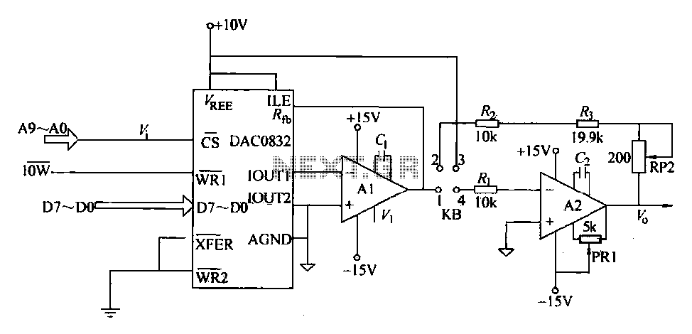
The DAC0832 is a digital-to-analog converter (DAC) chip designed for integration with computer bus systems. It features an 8-bit resolution and operates with a single power supply ranging from 5 to 15 volts. The device is compatible with TTL...
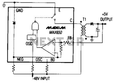
The Max650 switching regulator generates a regulated 5 V output from large negative voltages, such as the -48 V commonly found on telephone lines. This power supply requires several external components, including a transformer, and is capable of delivering...
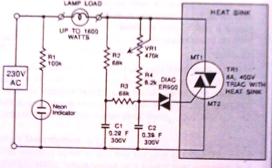
This dimmer is designed to control illumination effectively, with a power handling capacity that exceeds 1600 watts, significantly surpassing the typical 300-watt dimmers. The circuit utilizes a triac rated at 400 PIV and 8 amperes, while component VR1 allows...
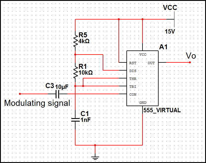
In pulse position modulation, the amplitude and width of the pulses are kept constant, while the position of each pulse with reference to the position of the reference pulse is changed according to the instantaneous sampled value of the...