
1000 watt power inverter schematic
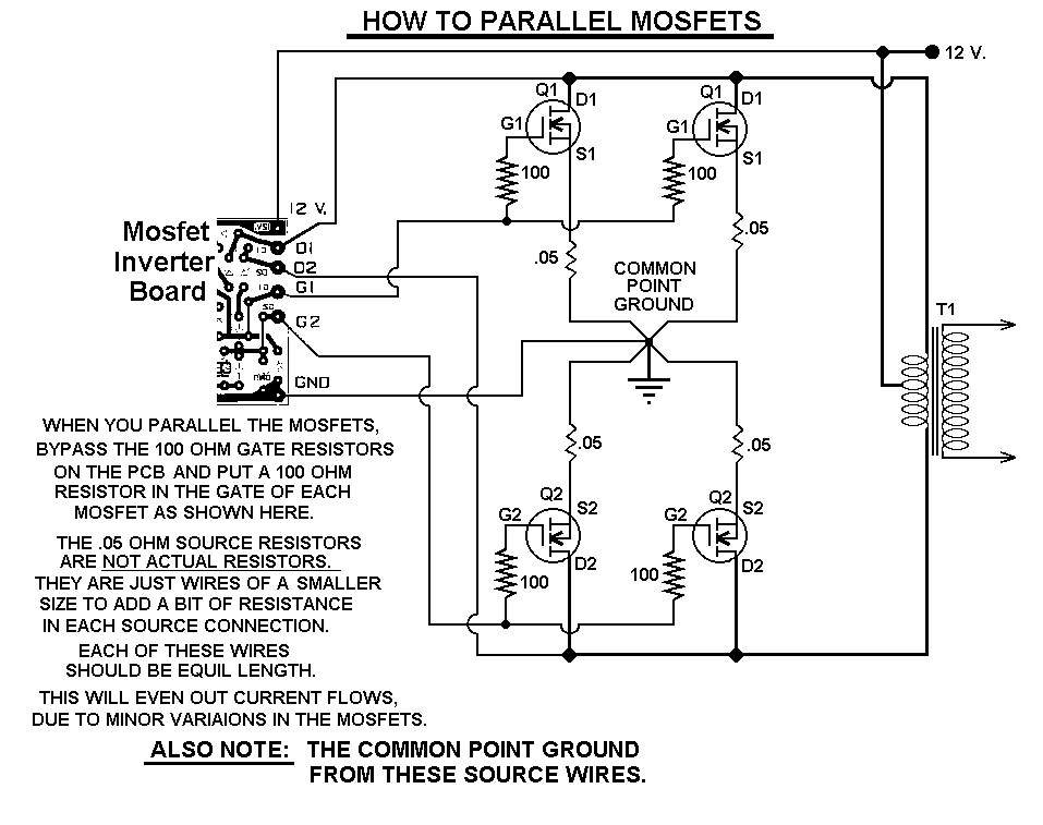
The 1000-watt power inverter circuit is designed to convert DC voltage into AC voltage, making it suitable for powering various electronic devices. The core component, the RF50N06 MOSFET, features a robust rating of 60 volts and 50 amps, allowing it to handle substantial power levels efficiently. When higher output is required, additional RF50N06 MOSFETs can be paralleled to increase the overall current capacity, ensuring that the inverter can meet the demands of more power-intensive loads.
In the schematic, the MOSFETs are typically arranged in a half-bridge or full-bridge configuration, which is essential for generating the desired AC waveform. The gate drive circuitry must be carefully designed to switch the MOSFETs on and off at the appropriate frequency, commonly in the range of several kilohertz, to produce a stable output waveform. A pulse-width modulation (PWM) technique may be employed to control the output voltage and frequency, providing versatility for different applications.
Incorporating a fuse in the power line is a critical safety measure. It protects the circuit from overcurrent situations that could lead to component failure or fire hazards. The fuse should be rated appropriately for the maximum expected current to ensure reliable operation while safeguarding the circuit.
The output transformer plays a vital role in this inverter circuit. It steps up the voltage to the desired level for AC applications. The choice of transformer affects the efficiency and performance of the inverter, and experimenting with different transformer designs can yield improved results. Users are encouraged to explore custom transformer configurations to optimize power output and efficiency based on their specific needs.
Overall, this power inverter circuit is a versatile solution for converting DC power into AC power, suitable for a wide range of applications, from small electronic devices to larger appliances, depending on the transformer and load configuration used.This 1000 watt power inverter circuit diagram based on MOSFET RF50N06. If you want more power then add additional MOSFET paralleled at RF50N06. This MOSFETS are 60 Volts and 50 Amps as rated. It is necessary to connect a FUSE with the power line and always a LOAD have to connected while power is being applied. The output power of this inverter is u p-to 1k watt, it depends on output power transformer. You can use your custom transformer with experimenting for best result. 🔗 External reference
Related Circuits
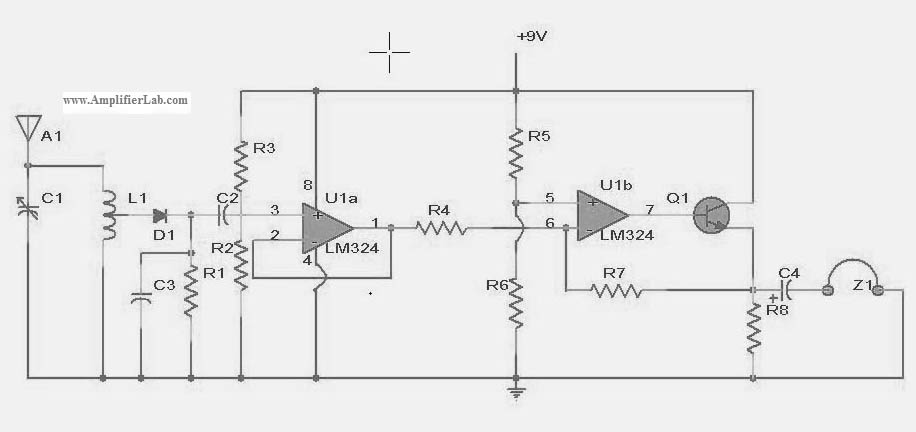
The following circuit illustrates a power amplifier electronic circuit, specifically a tube audio RF amplifier circuit diagram. This circuit is based on the LM324 integrated circuit. The power amplifier circuit utilizing the LM324 operational amplifier is designed to enhance audio...
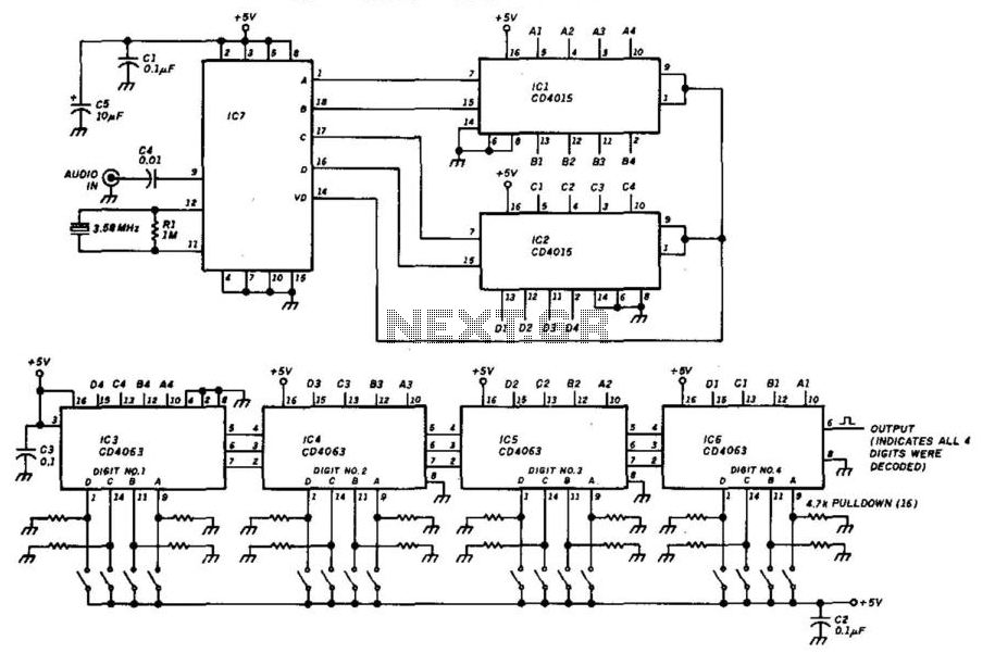
This decoder will respond to a preselected 4-digit DTMF number. IC7 is a Radio Shack IC device (part #276-1303). The logic is all CMOS. The digits are selected by SW1 and SW2, a pair of 8-position DIP switches. The described...
There are at least three different versions of this circuit. The first DM-2 version utilized the MN3005 BBD and the MN3101 Clock Driver IC (PCB marking: ET5214-510). Later, the clock driver was changed to the MN3102, and the BBD...
This RF amplifier ensures the power required to boost a small transmitter. Depending on the input RF power, power supply, and transistor, this amplifier can boost the signal. The RF amplifier is a critical component in various communication systems, designed...
The circuit below demonstrates how to power one or two LEDs from a 120-volt AC line. It utilizes a capacitor to reduce the voltage and a small resistor to limit the inrush current. As the capacitor needs to allow...
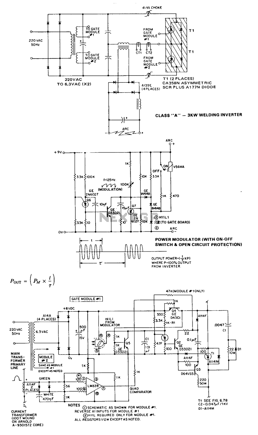
The circuit operates without significant added complexity and has a natural tendency to run away under no-load (high Q) conditions. The 20-kHz control circuit addresses these issues by feeding back into the asymmetrical thyristor trigger pulse generators signals that...