
Low-Power Touch-Tone Decoder
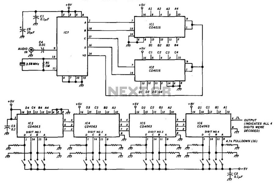
The described circuit employs a DTMF (Dual-Tone Multi-Frequency) decoder that is designed to recognize a specific 4-digit number. The core component, IC7, is a CMOS-based integrated circuit from Radio Shack, identified by the part number 276-1303. This IC is capable of interpreting the audio tones generated by a DTMF keypad, converting them into digital signals that correspond to the pressed keys.
User interaction is facilitated through two 8-position DIP switches, labeled SW1 and SW2. These switches allow for the selection of the desired DTMF digits by configuring the binary inputs that the decoder IC reads. Each switch can be set to either a high or low state, representing binary values that correspond to the DTMF digits 0-9 and the additional symbols such as *, #, A, B, C, and D.
The overall logic of the circuit is implemented using CMOS technology, which is known for its low power consumption and high noise immunity. This makes the circuit suitable for battery-operated devices or applications where power efficiency is critical. The output from the decoder can be used to trigger other components in a system, such as microcontrollers or relays, enabling various applications such as remote control systems, automated dialing, or access control mechanisms.
In summary, this DTMF decoder circuit utilizes a dedicated CMOS IC to recognize a specified 4-digit input, selected via DIP switches, and can interface with other electronic components for further processing or action based on the detected DTMF tones. This decoder will respond to a preselected 4-digit DTMF number. IC7 is a Radio Shack IC device (part #276-1303 ). The logic is all CMOS. The digits are selected by SW1 and SW2, a pair of 8-position DIP switches. 🔗 External reference
Related Circuits
This is a surround sound decoder. With this circuit, you can divide the 2-channel (right and left channel) stereo output into 4-channel output, which includes the right channel, left channel, center output, and rear output. This circuit will enhance...
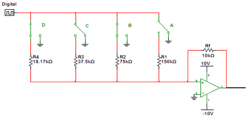
Encoders and decoders are circuits that convert analog signals to digital signals and digital signals to analog signals. The input is in digital form, while the output is a continuous sine wave or analog wave. Encoders and decoders play a...
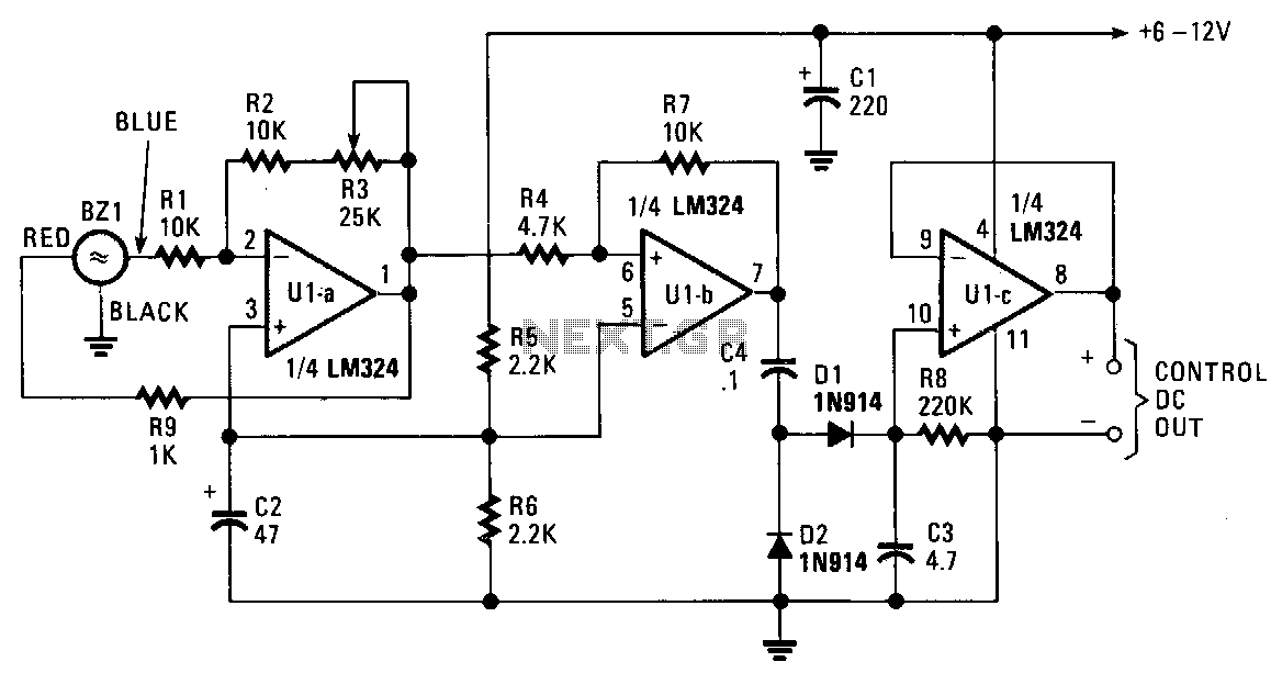
The piezo transducer functions as both a sound pickup device and a frequency-selective filter. By adjusting the gain of the operational amplifiers (op-amps), the oscillator can be configured as a sensitive and frequency-selective tone decoder circuit. When the gain...
This is an image Schematic. No Description available. The provided input indicates that there is a schematic image, but no additional descriptive information is available regarding its components, functionality, or application. In the context of electronic schematics, such images...
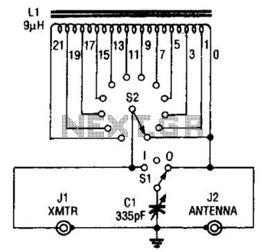
This antenna tuner is designed for low-power transmitters or shortwave receivers with a maximum power output of 5 watts. The switch S2 is used to select the inductance, while S1 connects a 365-pF capacitor either to the transmitter or...
This circuit features a white LED-based emergency light that provides several benefits. It is exceptionally bright due to the incorporation of white LEDs. The light activates automatically when the mains supply is interrupted and deactivates when mains power is...
Warning: include(partials/cookie-banner.php): Failed to open stream: Permission denied in /var/www/html/nextgr/view-circuit.php on line 713
Warning: include(): Failed opening 'partials/cookie-banner.php' for inclusion (include_path='.:/usr/share/php') in /var/www/html/nextgr/view-circuit.php on line 713