
Simple 7-Segment Counter Circuit
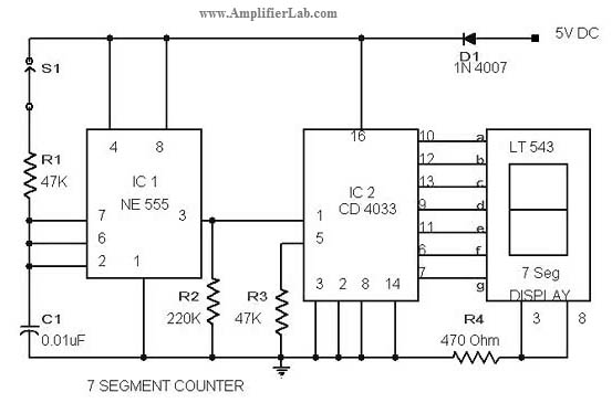
The 7-segment counter circuit utilizing the CD4033 integrated circuit (IC) is designed to display decimal digits from 0 to 9 on a 7-segment display. The CD4033 is a BCD (Binary-Coded Decimal) counter that can drive a 7-segment display directly, making it an ideal choice for this application.
The circuit typically includes the following components: the CD4033 IC, a 7-segment display, resistors for current limiting, and a clock signal source, which can be generated by a 555 timer or any other clock generator circuit. The CD4033 operates by counting pulses received at its clock input, incrementing the count with each pulse.
The output of the CD4033 is in binary-coded decimal format, which is then decoded to drive the 7-segment display. Each output pin of the CD4033 corresponds to a specific segment of the 7-segment display, allowing the display to represent the counted number visually.
Power supply connections are also essential; the CD4033 requires a DC power supply, typically in the range of 3V to 15V. Proper grounding and bypass capacitors should be included to ensure stable operation.
In summary, the 7-segment counter circuit employing the CD4033 IC is a straightforward yet effective design for visual numerical representation, suitable for various applications such as timers, clocks, and digital counters.The circuit diagram of 7 segment counter circuit has been published here. This circuit consists of counter IC CD 4033 as its central part. 🔗 External reference
Related Circuits
In 2011, designing a frequency converter circuit typically involves selecting an integrated circuit (IC) that meets specific requirements regarding gain and mixer spurious products, along with adding a couple of filters and a power supply. Often, the oscillator is...
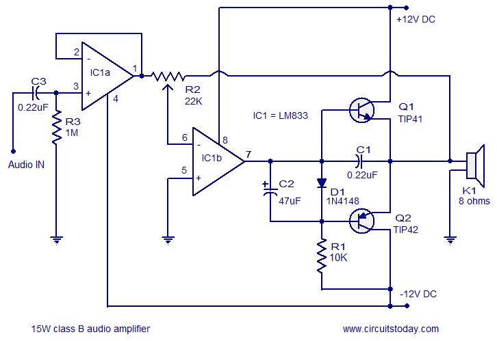
A 15 Watts Class B audio amplifier circuit is designed using a dual op-amp LM833. The schematic diagram is provided, and a potentiometer allows for volume control. The 15 Watts Class B audio amplifier circuit utilizes the LM833 dual operational...
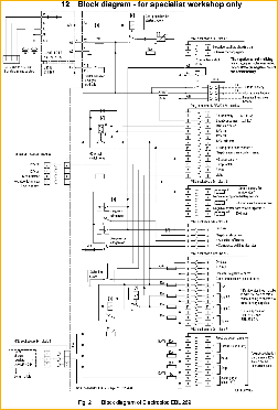
The following circuit illustrates an Elektroblock circuit diagram utilizing a 12V power supply. Features include various control and monitoring functions, with the specification of an 18 A LAS 1218 component. The Elektroblock circuit is designed to operate with a 12V...
The circuit measures distances using a modulated laser. It features a fixed voltage regulator (7805) that provides a stable +5 V source, followed by an LM317 adjustable voltage regulator to supply exactly 3 V to the diode laser module,...
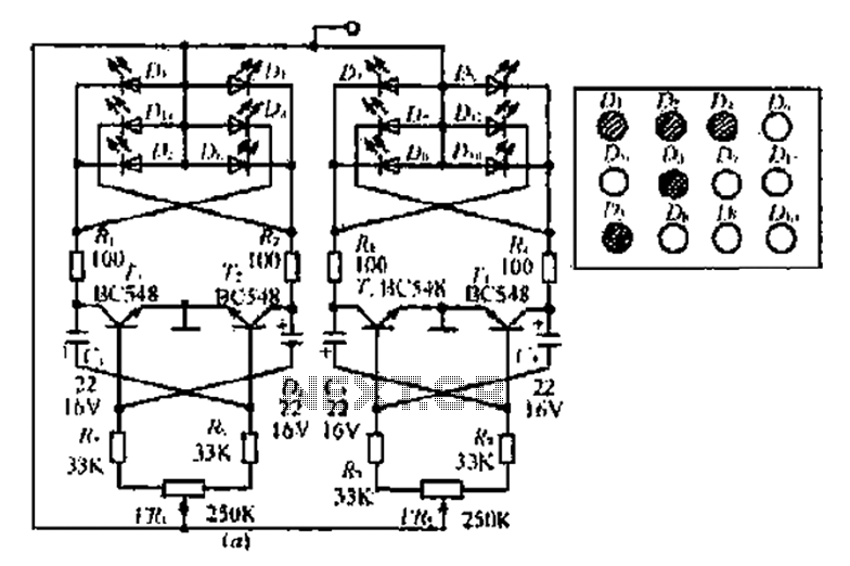
A circuit involving oscillations is composed of a Houle Wang oscillator that utilizes a transistor configuration with components labeled Ti, n, and n, along with a composition of Q constants for the cycle. The waveform can be modified by...
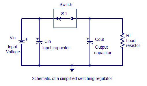
Switching regulators operate by drawing small amounts of energy from the input source and transferring it incrementally to the output. This is achieved using an electronic switch, which functions at a predetermined frequency, acting as a gate between the...
Warning: include(partials/cookie-banner.php): Failed to open stream: Permission denied in /var/www/html/nextgr/view-circuit.php on line 713
Warning: include(): Failed opening 'partials/cookie-banner.php' for inclusion (include_path='.:/usr/share/php') in /var/www/html/nextgr/view-circuit.php on line 713