
100Khz sine oscillator
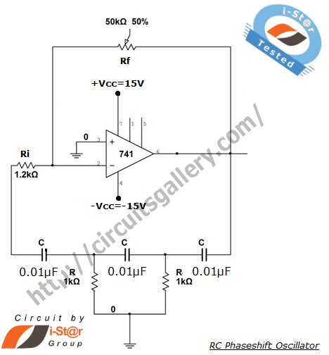
To construct a phase-shifted oscillator circuit, begin by selecting a suitable op-amp that can operate within the desired frequency range. The three resistors (R1, R2, R3) and capacitors (C1, C2, C3) should be chosen to set the phase shift accurately. The adjustable resistor allows for fine-tuning of the oscillation frequency, ensuring that the circuit can adapt to various applications. The configuration typically involves connecting the op-amp in a feedback loop, where the output is fed back through the phase-shifting network composed of the resistors and capacitors.
The gain of the amplifier is critical for maintaining the oscillation. The additional resistors (R4 and R5) set the gain of the op-amp, and their values must be calculated to achieve the necessary 18 dB gain. This can be done using the formula for non-inverting amplifiers, where the gain (A) is given by A = 1 + (R5/R4).
When implementing the R/C filter to trim harmonics, it is essential to select R and C values that create a corner frequency appropriate for the target application. The corner frequency (fc) can be calculated using the formula fc = 1/(2πRC). Adjusting these values allows for control over the filter's response and the extent of harmonic distortion.
In cases where the output needs to drive a significant load, it is advisable to integrate a secondary amplification stage to ensure that the amplitude remains consistent. This stage can be another op-amp or a transistor-based amplifier, depending on the load requirements.
The overall design should ensure that the initial output waveform is symmetrical, as any asymmetry can lead to increased distortion that cannot be corrected by the R/C filter. Regular testing and adjustment may be necessary to optimize performance and ensure that the oscillator meets the desired specifications.All you really need is a decent opamp, three resistors, three caps. Make one of the resistors adjustable, otherwise all components same value. It`s called a phase shifted oscillator and it has very good, very low distortion. The gain of the amplifier is set by two additional resistors. That`s one way. Another is a simple 555 square wave oscillator , then use an R/C filter to, Trim, the harmonics (edges, )which will have produce bit of distortion but you can control that by setting the R/C corner frequency, then make up for lost gain with a second stage of gain to get back your amplitude. The start though is a good accurate square wave, symmetrical, because the R/C filter will not, can not fix asymmetry.
Is a web site that shows the principal of the phase shifter oscillator circuit and others as well. Each of the three phase shift stages attenuates the signal -6 dB so the amplifier needs 3G—6 or 18 dB of gain, which is a gain of 8, not hard to do and is more linear given lower gain. This circuit though is just an NPN transistor, simple but it is load sensitive so that could be a problem.
Op amps would work better in this application if you need to drive some significant load. 🔗 External reference
Related Circuits

The circuit serves as a signal source for calibration level meters or sensor-driven differential transformers. The oscillation frequency is determined by the 74HC04, producing a frequency of 1 kHz through resistor R. The supply voltage of the circuit changes...
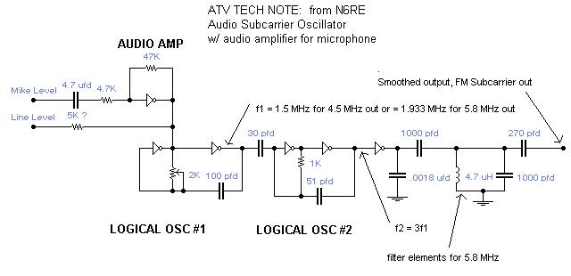
A single integrated circuit (IC) provides all amplifiers: the 74HC04 Hex Inverter, which is a digital component. The second oscillator synchronizes to three times the frequency of the first oscillator, thereby tripling the frequency modulation (FM) deviation. Utilizing the...
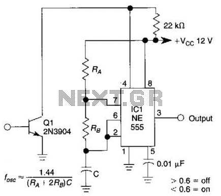
This gated 1-kHz oscillator provides press-to-turn-off functionality, along with waveforms available at the output of pin 3 and across capacitor C1. The gated 1-kHz oscillator circuit is designed to generate a square wave output at a frequency of 1 kHz....
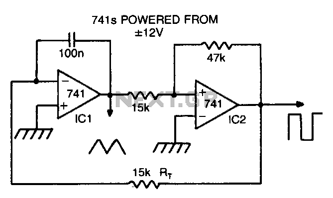
By making Rt variable, it is possible to alter the operating frequency over a 100 to 1 range. The versatile triangle/square wave oscillator has a possible frequency range of 0 Hz to 100 kHz. The described circuit features a variable...
One of the simplest methods of metal detection is through a beat frequency oscillator. The circuit consists of two balanced oscillators: one provides a reference signal, while the other acts as the detector element. The frequency of the reference...
Unlike conventional small-signal methods, employing large-signal, time-domain design techniques facilitates the development of low-noise grounded-base oscillators suitable for VHF/UHF applications. The implementation of large-signal, time-domain design techniques in the creation of grounded-base oscillators represents a significant advancement in the field...
Warning: include(partials/cookie-banner.php): Failed to open stream: Permission denied in /var/www/html/nextgr/view-circuit.php on line 713
Warning: include(): Failed opening 'partials/cookie-banner.php' for inclusion (include_path='.:/usr/share/php') in /var/www/html/nextgr/view-circuit.php on line 713