
A Simple Metal Detector Circuit Using Beat Frequency Oscillator (BFO)
The metal detector circuit operates on the principle of frequency modulation, where the presence of a metallic object alters the inductance of the detector oscillator. This change in inductance leads to a shift in the resonant frequency of the LC oscillator, which is sensitive to nearby conductive materials. The reference oscillator, typically designed with a stable RC configuration, serves as a baseline frequency to which the detector oscillator can be compared.
The use of a CMOS 4011 chip for the NAND gates is advantageous due to its low power consumption, making it ideal for portable applications powered by batteries. The LM7805L voltage regulator ensures that fluctuations in battery voltage do not affect the reference frequency, thereby enhancing the reliability of detection.
For optimal performance, the circuit should be calibrated in an environment free of metal objects, allowing for precise tuning of the oscillators. The tuning process is critical, as it establishes the baseline frequency and ensures that the circuit is responsive to the detection of metal. The output audio signal serves as an alert mechanism, indicating the presence of metal when the frequency difference between the reference and detector oscillators falls within audible range.
This design is suitable for hobbyists and can be further enhanced by incorporating additional features such as sensitivity adjustments or visual indicators for metal detection, broadening its applicability in various metal detection scenarios.One of the simplest method of metal detecting is by beat frequency oscillator. Basically, the circuit consist of two balanced oscillator. One oscillator provides the reference signal, and other oscillator is acting as the detector element. The reference oscillator`s frequency is fix, while the detector oscillator is variable depending on the prese
nce of a metal. The reference oscillator can be constructed using various circuit topology: inductor-capacitor (LC), resistor-capacitor (RC), or even a crystal (quartz) oscillator. While the reference oscillator can be implemented using various circuit topology, the detector oscillator always use inductor-capacitor topology, because the mechanism will be using the magnetic induction property of the detected object, and the inductor component of the detector oscillator will be the detecting probe.
With the absence of a metal near the detector probe (the inductor component of the detector oscillator), the detector oscillator is tuned to have same frequency as the reference oscillator. The output of the detector oscillator and the reference oscillator output is mixed using hetero-dyne mixer circuit, producing a beat frequency output of zero Hz, or a very low frequency if both oscillator is slightly unbalanced.
In the presence of a metal near the detector probe, the detector oscillator will shift it`s frequency, and the mixer output will produce a tone with frequency equal to the difference of the reference and the detector frequency. The figure below shows one of the simple metal detector circuit. You can see the reference circuit is a simple RC circuit, and its frequency is determined by R1-P2-C1.
The detector oscillator is an LC oscillator with the frequency is determined by the L1-C2-C3 values. The NAND gates use CMOS 4011 chip, a low power component that is suitable for this battery-operated circuit. You can see that this chip is supplied by a 5V voltage coming from an LM7805L regulator. You might wonder what the purpose of this regulation is, since the power supply come from a 9V battery and the CMOS gates can handle the voltage of 3-15 Volt.
The main purpose of the regulator is to keep a constant voltage source for the reference oscillator frequency stability, since the frequency is affected by the power supply voltage variation as the battery voltage drops in the long time of usage. To tune the circuit, plug a headphone at the output, and remove any metal around the inductor L1. Set the volume control P1 around at center. Set the reference oscillator tuner P2 at the maximum or minimum position, you should hear no sound since the frequency should be in ultrasonic range.
Turn slowly P2 until you hear a very high audio frequency, continue turning the pot until the frequency is decreasing and stop turning when the note is just disappeared (the frequency is decreased down below 20 Hz). After this, you can test the circuit by placing a metal near the inductor L1 and now the output will give an audible frequency as the detection alert.
[Circuit`s schematic diagram source: hobby-hour. com] 🔗 External reference
Related Circuits
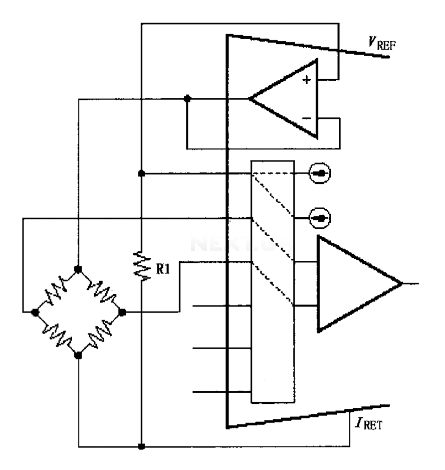
The circuit for the bridge excitation voltage XTR108 is linearized using adjusted algorithms that correspond to the linearization of the RTD response. The excitation voltage VEX is defined as 2IREFR1, where VEX represents the excitation voltage applied at both...
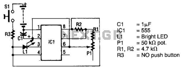
The circuit utilizes a 555 timer integrated circuit (IC) to drive an ultrabright LED. The output generated is a pulsing red light that can be focused using lenses. An ultrabright Stanley LED, which produces an output of 300 millicandela,...
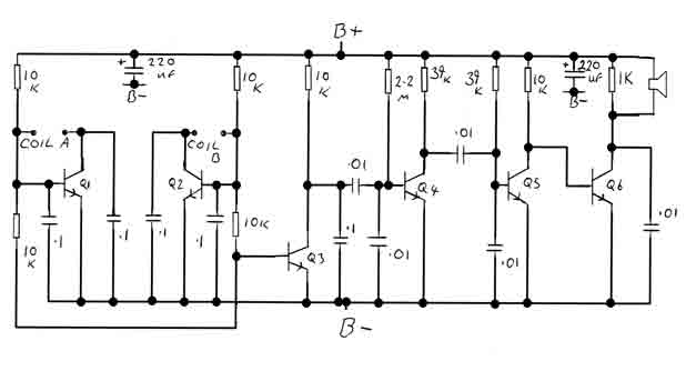
By adjusting the oscillators so their frequencies are very nearly the same, the difference between them is made audible as a beat note. This beat note changes slightly when the search loop is moved over or near to a...
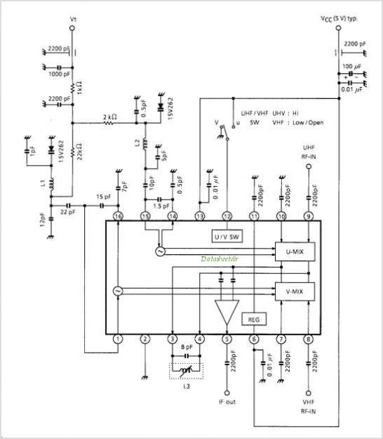
TA1317ANG is a deflection processor integrated circuit (IC) designed for large and wide picture tubes. It includes an electronic width (EW) correction circuit, a vertical distortion correction circuit, and a dynamic focus correction circuit. The device can control various...
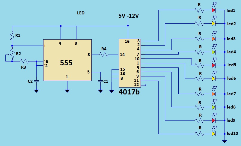
This is a LED sequencer circuit where 10 LEDs light up and turn off sequentially, creating a chasing effect. This simple circuit is suitable for designing lighting decorations on Christmas trees. It can also be used for lighting animations...
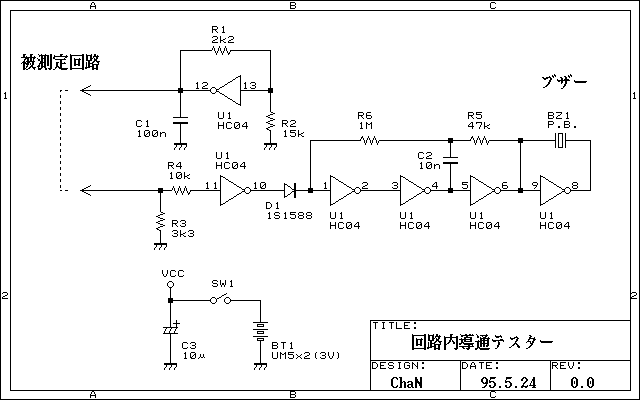
Continuity tester to check continuity in the circuit (Insakittochekka) is. The continuity check over the circuit board wiring that can be checked at a lower voltage semiconductors do not conduct contained in the circuit, you can just check the...
Warning: include(partials/cookie-banner.php): Failed to open stream: Permission denied in /var/www/html/nextgr/view-circuit.php on line 713
Warning: include(): Failed opening 'partials/cookie-banner.php' for inclusion (include_path='.:/usr/share/php') in /var/www/html/nextgr/view-circuit.php on line 713