
Sine wave converter circuit

The circuit utilizes a 74HC04 hex inverter, which is integral for generating the oscillation frequency. The inverter's output can be configured to produce a square wave signal, which is a fundamental aspect of many signal generation applications. The resistor R is crucial in setting the frequency of oscillation; by adjusting its value, the output frequency can be finely tuned to meet the requirements of various calibration tasks.
The supply voltage (Tl) is dynamically influenced by the amplitude of the output signal, allowing for a responsive design that adapts to varying signal levels. This characteristic is particularly useful in applications where sensor signals may fluctuate, ensuring consistent performance across a range of operating conditions.
The switch plays a pivotal role in shaping the output waveform. By toggling the switch, the output can be transformed from a varying voltage level into a square wave signal. This square wave is then subjected to low-pass filtering, which effectively attenuates higher frequency components that are not desired in the final output. The design of the low-pass filter is critical; it typically consists of passive components such as resistors and capacitors, which work together to smooth out the square wave into a cleaner sine wave.
The performance of the low-pass filter directly affects the fidelity of the output waveform. The cutoff frequency of the filter must be carefully selected to balance between adequate signal smoothing and maintaining the integrity of the desired frequency component. Additionally, depending on the application, a series of filters may be utilized to achieve the desired level of signal purity and distortion minimization.
In summary, this circuit design is versatile and can be adapted for various calibration and sensing applications, with careful consideration given to component selection and configuration to optimize performance.The circuit can be used as the signal source of calibration level meter or sensor-driven differential transformer. Circuit oscillation frequency is determined by the 74HCO4, and it is transferred lkHz by R. The supply voltage of Tl changes with the amplitude output. The switch turns the output voltage into square wave, then it will get sine wave b y filtering the high frequency by low-pass filter. Waveform distortion depends on the performance of the filter, and the series of filter is used according to the need. 🔗 External reference
Related Circuits
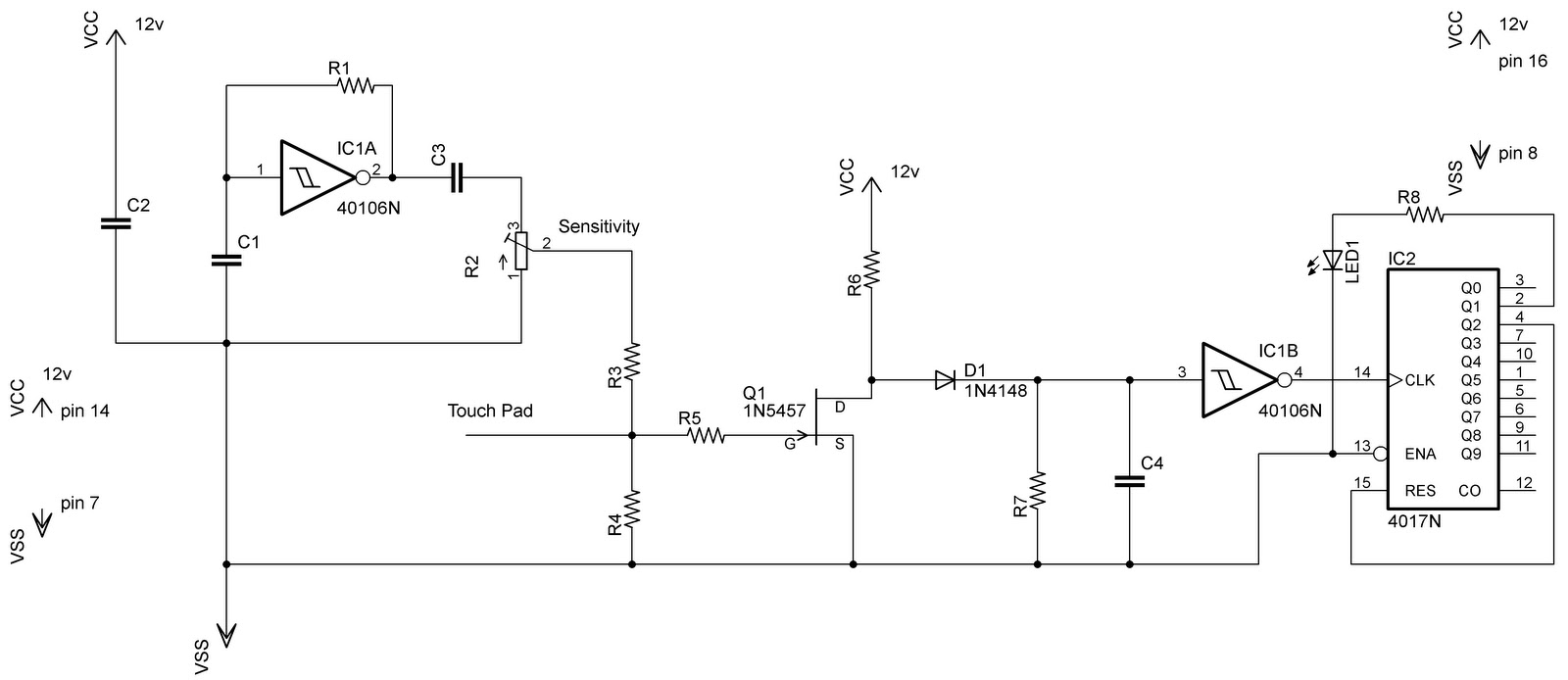
In the previous post regarding a capacitive touch switch, the output was activated only while the touch was maintained. This means that the circuit would drive the load only during the touch, and once the touch was removed, it...
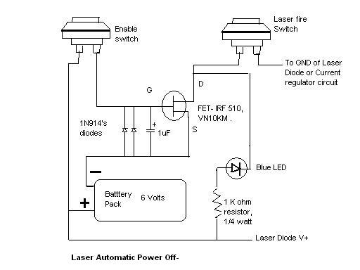
Here is the automatic laser power-off circuit schematic. This circuit features a visible power indication. In this case, the ground is connected on one side. The automatic laser power-off circuit is designed to enhance safety and efficiency in laser applications...
When the circuit is connected to hi-fi equipment or at both ends of the electronic instrument's speaker, the audio level can be modulated to a 500W lamp proportionally. This is achieved using three appropriate sets of audio filters and...
Metal Detector Circuit Overview The metal detector circuit is an electronic circuit that is specifically designed to detect metal that lies deep in the water. The metal detector circuit operates on the principle of electromagnetic induction, where a coil generates...
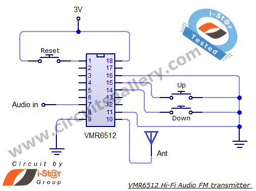
This article provides the circuit schematics for an FM transmitter along with the necessary explanations. The primary component utilized is the VMR6512 IC, a highly integrated FM audio signal transmitter chip designed for Hi-Fi audio applications. This chip can...
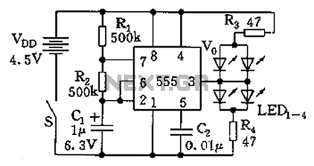
The circuit consists of a 555 timer and a light-emitting diode (LED) array. The 555 timer, along with resistors R1, R2, and capacitor C1, forms an astable multivibrator configuration. The oscillation frequency is calculated using the formula f =...