
100khz square wave generator
The audio signal generator is designed to produce square wave test signals suitable for evaluating audio amplifiers. The circuit operates within a frequency range that extends beyond standard audio frequencies, allowing engineers to observe the amplifier's behavior under conditions that may not be encountered during typical audio playback. The inclusion of a square wave signal at 100 kHz serves as a critical test point for identifying overshoot characteristics and other non-linear behaviors that may arise due to the amplifier's feedback mechanisms.
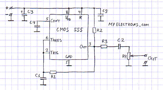
The generator utilizes a CMOS 555 timer in astable mode, which is known for its reliability and ease of use. To enhance the circuit's performance, particular attention is given to minimizing output ringing and power line disturbances. This is achieved through careful component selection and layout, ensuring that the output signal remains clean and stable.
The design incorporates a set of DIP switches, allowing users to select various frequencies as needed. Each frequency setting is achieved by adjusting the timing components—resistors and capacitors—within the 555 timer circuit. This modular approach provides flexibility and adaptability for different testing scenarios.
Power supply considerations are paramount; thus, the circuit is designed to operate effectively with either battery power or a low-frequency transformer-based wall adapter. The recommendation against switching power supplies is based on their potential to introduce noise and high-frequency spikes that could compromise the integrity of the test signals.
Additionally, the inclusion of reverse polarity protection safeguards the circuit against incorrect power supply connections, enhancing reliability during operation. Overall, this audio signal generator represents a practical and efficient solution for audio testing applications, providing engineers with the tools necessary to assess amplifier performance with precision.The musical signal`s form does never resemble a square wave. The frequency range perceived by an average adult hardly goes above 17KHz. Hence I do not give a dime to those heated discussions whether it`s appropriate to test audio amplifiers using a 100KHz meander signal. But being an electronic engineer in my heart as well as by education and pass ion - I can assure you that giving an audio amplifier a try with 100KHz square wave test signal can reveal quite some technical qualities (or lack of those) in the design. Overshots caused by negative feedback loops or signal slopes formed by input/Miller capacitances are amongst things that are easier to observe with meander than when using sound-frequency test signal.
Before turning to the true and tried CMOS 555 I tested several oscillators based on old soviet 561 › 7, 561 › 2, as well as 74HC04 and 74HCT04; the last unsuccessful attempt was made using LM555. All the attempts listed above have failed due to the horrible ringing the chips were generating at its outputs.
The current spikes in the power line were also quite hard to tolerate. Therefore I came up with only two budget solutions: People who love micro-controllers may start laughing at me here. Honestly I was also tempted to build a universal square wave generator based on ATmega-8 that I had at hands.
But somehow I am too lazy to program when the same result can be achieved by a comparable amount of soldering without turning on that annoying thing (computer. And to tell you the truth I strived to have as minimal of those high bandwidth current spikes as possible - in order to test quality audio equipment I wanted to have a quality test signal as well.
Regardless the fact that the generator`s bill of materials amounted for just a few bucks. Obviously testing audio amplifiers with the test signal well centered relative to the ground is very convenient. On the other hand adding DC shift helps to qualify how well the servo-circuitry works - the one that is responsible for assuring the steady zero DC at the output.
Thus having a choice between "open" and "closed" output was a good thing to build in the test signal`s generator: just install a switch or a "jumper" that would short C2. Once I heated up my soldering iron I did not want to stop with a single 100KHz frequency. By adding a simple line of DIP-switches and few extra capacitors and resistors we are able to cover pretty wide frequency range.
The finished generator circuit can be fed from 4 AA batteries or a simple wall-brick. I strongly suggest you staying away from switching power supplies here and use an old good low frequency transformer. Since I like good CMOS 555 a lot - I added the reverse polarity protection to this design. 🔗 External reference
Related Circuits
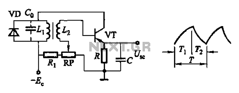
Common non-sinusoidal oscillator circuit, waveform and frequency formula - pulse wave oscillator - single-junction transistor blocking oscillator. The common non-sinusoidal oscillator circuit described is a pulse wave oscillator that utilizes a single-junction transistor in a blocking configuration. This type of...
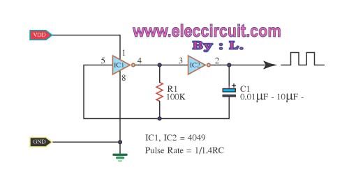
The inverter CMOS digital IC CD4049 is utilized to design a square wave oscillator generator. The CD4049 is a hex inverting buffer, which means it contains six independent inverters that can be used to generate square wave signals. This IC...
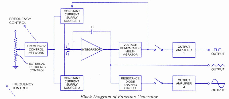
A function generator is a signal source capable of producing various types of waveforms as its output signal. The most common output waveforms include sine waves, triangular waves, square waves, and sawtooth waves. The frequencies of these waveforms can...
This sawtooth wave generator provides a sweep signal at output 1 and a synchronization output at output 2, which activates when the sawtooth wave returns to its starting point. The frequency of the sawtooth wave signal is calculated using...
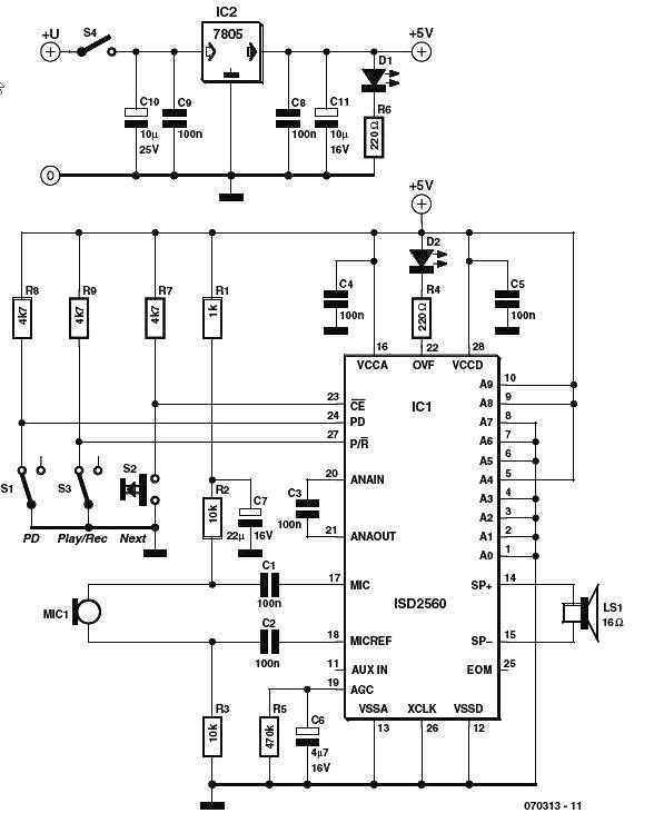
The voice generator scheme schematic diagram utilizes the ISD2500 series of chip-coders from Winbond, which encompasses all necessary components for recording and playback of voice messages. These chips feature microphone preamps with Automatic Gain Control (AGC), allowing compatibility with...
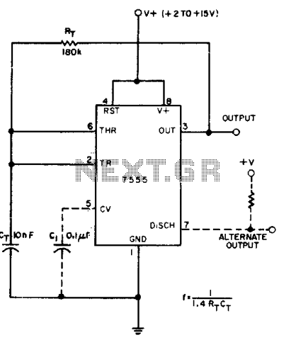
A CMOS timer generates true square waves because, unlike the bipolar 555, its output swings from rail to rail. The component values shown give a frequency of about 400 Hz. The CMOS timer circuit operates by utilizing complementary metal-oxide-semiconductor technology...