
robotic voice generator
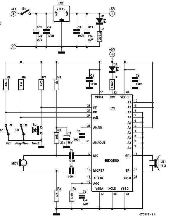
The ISD2500 series is designed for applications requiring high-quality audio playback and recording in a compact form factor. The microphone preamp with AGC enhances audio input quality by adjusting the gain to accommodate varying sound levels, ensuring clear recordings from inexpensive microphones. The output amplifier is capable of delivering sufficient power to drive small speakers, making it suitable for portable devices.
The integrated memory within the ISD2500 allows for the storage of voice messages, which can be recorded and played back multiple times. The oscillator generates the necessary clock signals for the chip's operation, while the ADC and DAC facilitate the conversion between analog audio signals and their digital representations, enabling efficient processing and playback of recorded audio.
In summary, the schematic diagram for the voice generator scheme using the ISD2500 series presents a complete solution for voice recording and playback, integrating essential components that work harmoniously to deliver high-quality audio performance in various applications.Voice generator scheme schematic diagram. The family of chip-coders ISD2500 firm Winbond contains almost everything you need to record and play back voice messages. As chips have mic preamps with AGC, working with the cheapest electret microphones, the output amplifier that runs on the speaker, memory, oscillator, ADC and DAC.
🔗 External reference
Related Circuits
This circuit utilizes the versatile MAX038 function generator. While some advanced features of this IC are disabled in this configuration, it is capable of generating sine, triangle, and square waves by adjusting the A0 and A1 pins (refer to...
This page contains links to various projects and items of interest for the RoboticsArt Studio class projects. The RoboticsArt Studio class projects encompass a range of innovative endeavors that integrate art and robotics. These projects typically involve the design, assembly,...
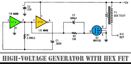
The schematic diagram below illustrates a high voltage generator circuit. This circuit employs a 4049 hex inverter configured as an oscillator, and it can utilize an ignition transformer from an automotive engine. A fly-back transformer may also be suitable....
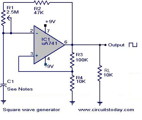
Square wave generator using uA741. Circuit diagram, theory, and working principle. The square wave generator utilizing the uA741 operational amplifier (op-amp) is a fundamental circuit widely employed in various applications, including signal processing, waveform generation, and timing applications. The uA741...
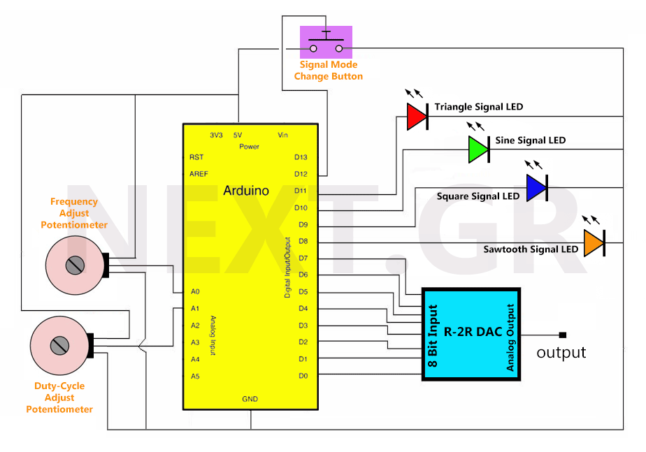
Once the circuit receives power, all variables are initialized, and the loop function runs continuously. Initially, all LEDs are off, and there is no output signal. Pressing the signal switch activates the first LED, indicating the output signal. The...
The NI 655X is a versatile high-speed digital product capable of interfacing with various technologies. This application note illustrates how to connect the NI 655X to Low Voltage Differential Signaling (LVDS) devices. LVDS is an emerging differential digital standard...