
Non-sinusoidal oscillator circuit waveform pulse wave oscillator single-junction oscillator
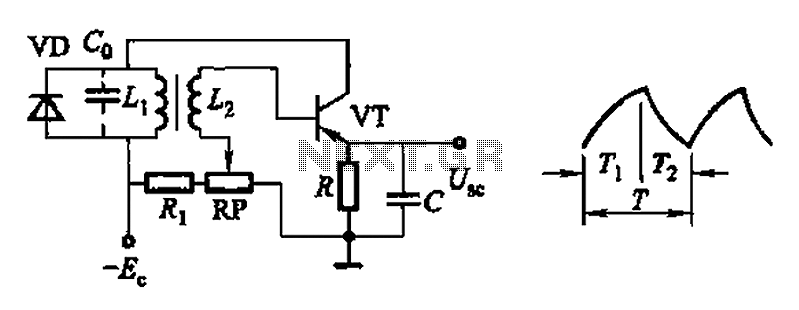
The common non-sinusoidal oscillator circuit described is a pulse wave oscillator that utilizes a single-junction transistor in a blocking configuration. This type of oscillator is characterized by its ability to generate square or pulse waveforms, which are essential in various electronic applications such as timing circuits, clock generators, and signal modulators.
In a typical single-junction transistor blocking oscillator circuit, the transistor operates in a switching mode. When the circuit is powered, the transistor is initially turned off, preventing current from flowing through the collector-emitter path. A capacitor is connected to the base of the transistor, charging through a resistor. Once the voltage across the capacitor reaches a certain threshold, the transistor turns on, allowing current to flow and rapidly discharging the capacitor. This action produces a pulse in the output.
The frequency of the output waveform can be determined by the values of the resistor and capacitor used in the circuit, as well as the characteristics of the transistor. The basic formula for the frequency (f) of the oscillator is given by:
f = 1 / (2 * π * R * C)
where R is the resistance in ohms and C is the capacitance in farads. This formula indicates that the frequency is inversely proportional to both the resistance and capacitance values; thus, increasing either the resistance or capacitance will decrease the frequency of the oscillation.
The waveform produced by this oscillator is typically a square wave, which can be further manipulated with additional components to achieve desired characteristics such as duty cycle and amplitude. The simplicity and effectiveness of the single-junction transistor blocking oscillator make it a popular choice in various electronic designs that require pulse generation. Common non-sinusoidal oscillator circuit, waveform and frequency formula - pulse wave oscillator - single-junction transistor blocking oscillator
Related Circuits
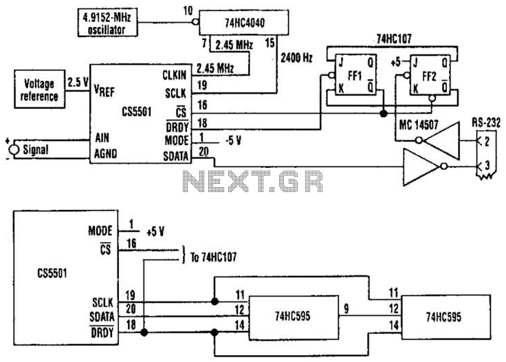
The CS5501 16-bit delta-sigma analog-to-digital converter continuously converts signals, outputting conversion words to its output register every 1024 cycles of its master clock, as it lacks a start convert command. By integrating a standard dual J-K flip-flop into the...
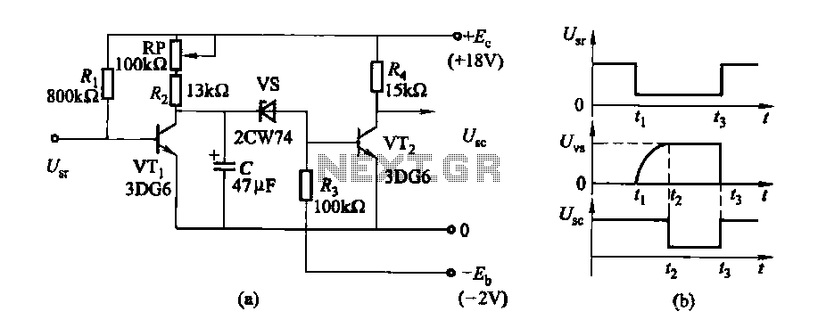
The delay time ranges from 0.5 to 3.5 seconds, which can be adjusted using the potentiometer RP to modify the delay duration. The circuit utilizes a timing mechanism that allows for the adjustment of delay intervals between 0.5 seconds and...
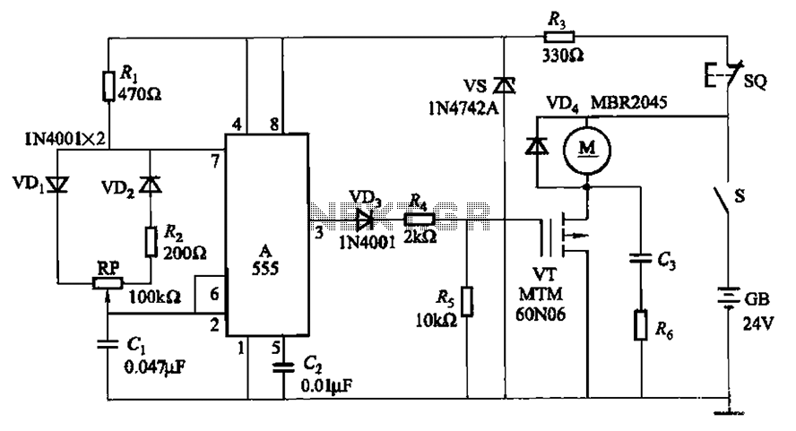
The adjustment potentiometer (RP) allows for modification of the duty cycle of a square wave generated by the 555 integrated circuit (IC) in New Zealand, enabling control of motor speed within a range of 0 to 100%. The circuit utilizes...
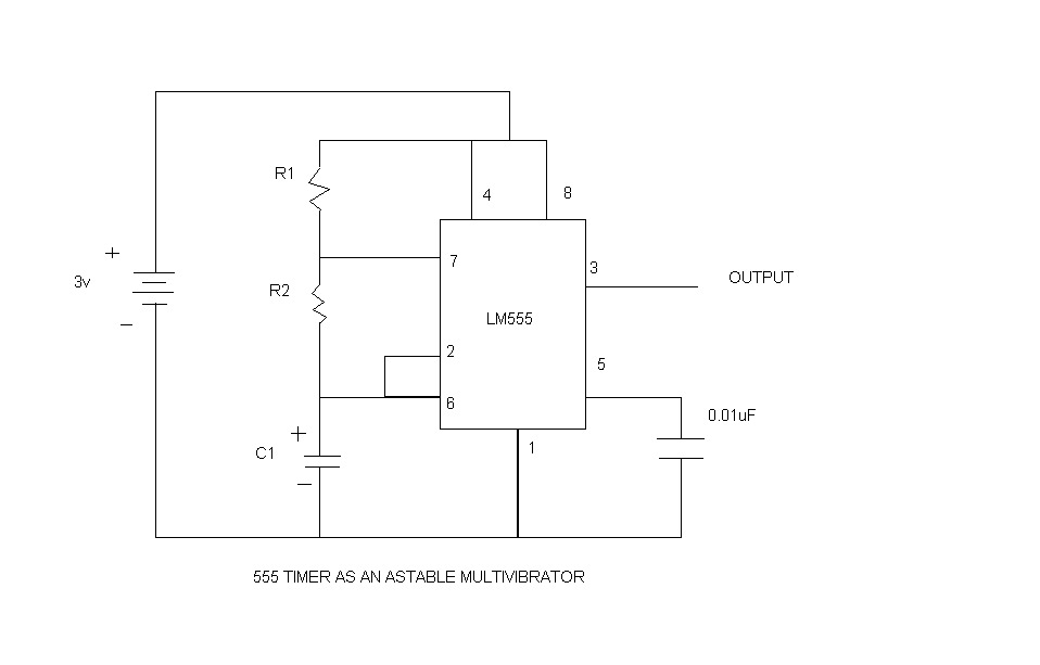
An astable multivibrator, commonly referred to as a free-running multivibrator, is a circuit that generates rectangular waves without the need for external triggering. The timing characteristics of this circuit are determined by the values of the resistors and capacitors...
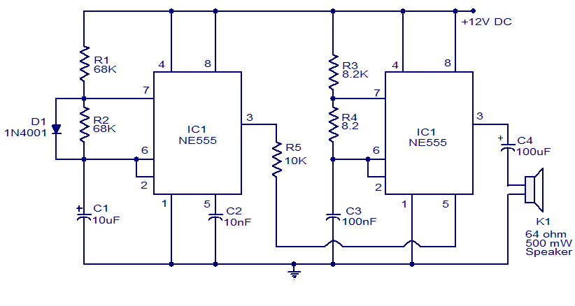
A variety of electronic circuits utilize the NE555 timer integrated circuit (IC). The circuit diagram presented illustrates a police siren based on two NE555 timer ICs, both configured as astable multivibrators. The circuit operates on a DC voltage supply...
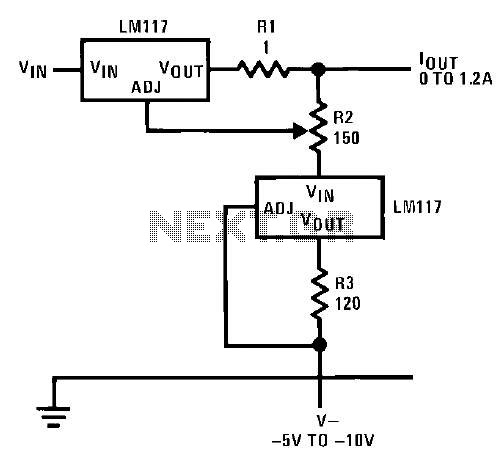
This circuit illustrates an adjustable regulator configuration that incorporates a voltage regulator. In this design, the LM117 regulator is utilized instead of the LM113 diode for reference. Both regulators necessitate a negative supply to function correctly with respect to...
Warning: include(partials/cookie-banner.php): Failed to open stream: Permission denied in /var/www/html/nextgr/view-circuit.php on line 713
Warning: include(): Failed opening 'partials/cookie-banner.php' for inclusion (include_path='.:/usr/share/php') in /var/www/html/nextgr/view-circuit.php on line 713