
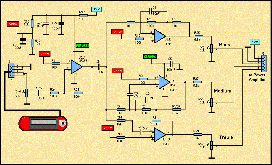
100W 420-450Mhz push-pull linear amplifier
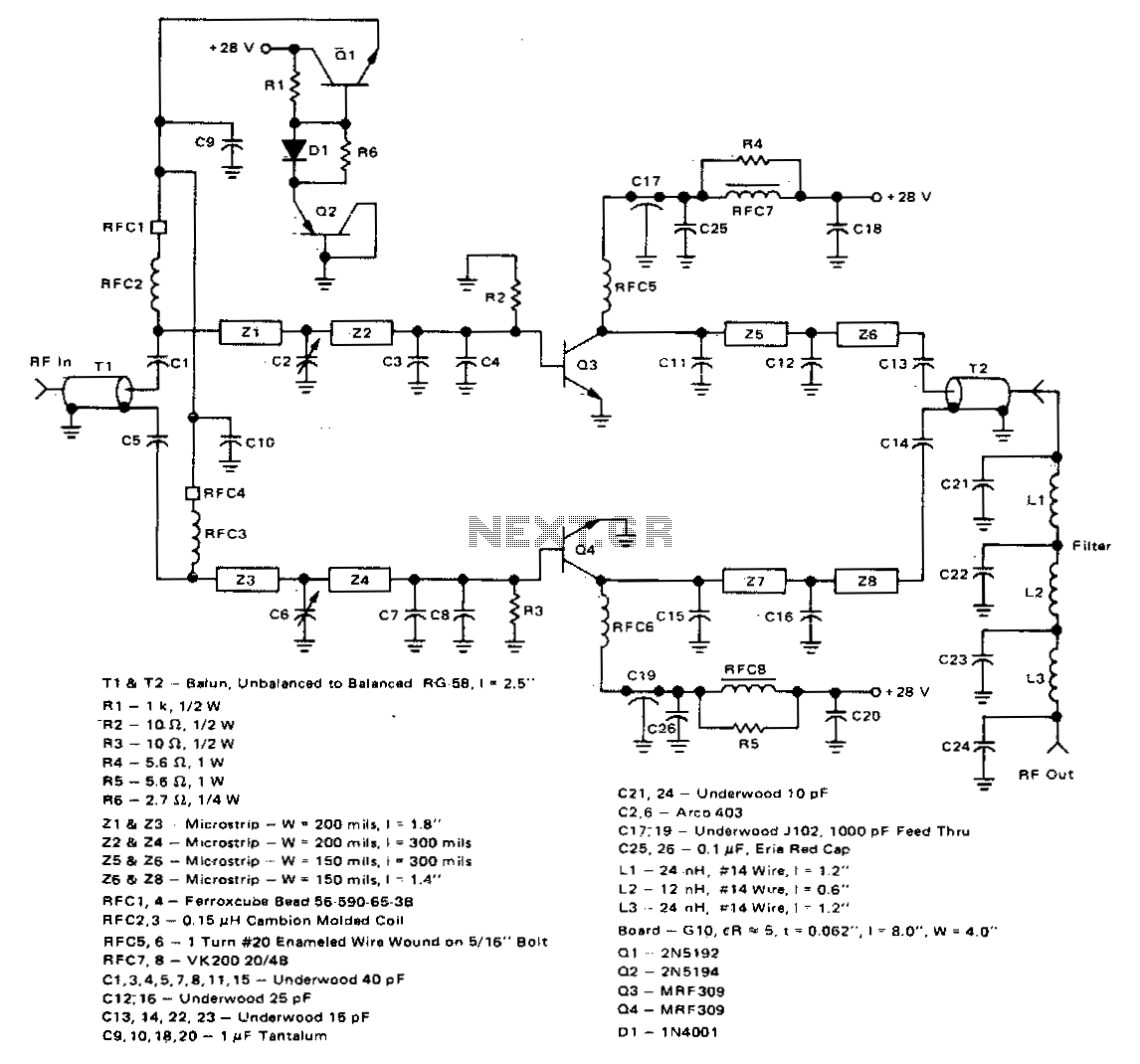
The 100-watt linear amplifier designed with two MRF309 transistors in a push-pull configuration presents a robust solution for RF amplification. The use of MRF309 transistors is advantageous due to their high-frequency capabilities and power-handling characteristics, making them suitable for applications within the specified frequency range of 420 to 450 MHz.
The amplifier requires a modest input drive of only 16 watts, which is efficient for achieving the desired output power of 100 watts. This low drive requirement helps in minimizing the overall power consumption and heat generation, contributing to a more reliable operation.
Operating at a supply voltage of 28 volts, the amplifier achieves a power gain of eight dB. This level of gain is sufficient for many RF applications, ensuring that the output signal is significantly amplified while maintaining signal integrity. The design also incorporates features that enhance performance, such as a maximum input standing wave ratio (SWR) of 2:1, which indicates good impedance matching and minimizes signal reflections that could lead to inefficiencies.
Harmonic suppression is another critical specification, with the amplifier providing suppression levels greater than -63 dB at the 100-watt output level. This feature is essential for reducing unwanted emissions and ensuring compliance with regulatory standards for spectral purity in RF transmission.
Furthermore, the amplifier exhibits an efficiency greater than 40%, indicating that a substantial portion of the input power is converted to output power, which is crucial for minimizing operational costs and thermal management. The circuit also demonstrates stability under varying load conditions, with the ability to handle a 3:1 collector mismatch at all phase angles. This characteristic is particularly important in real-world applications where load conditions may fluctuate, ensuring reliable and consistent performance of the amplifier across its operating range.
Overall, this linear amplifier design combines efficiency, power gain, and stability, making it suitable for various RF applications.This 100 watt linear amplifier may be constructed using two MRF309 transistors in push-pull, requiring only 16 watts drive from 420 to 450 MHz Operating from a 28 volt supply, eight dB of power gain is achieved along with excellent practical performance featuring: maximum input SWR of 2:1, harmonic suppression more than—63 dB below 100 watts output, efficiency greater than 40%, circuit stability with a 3:1 collector mismatch at all phase angles. 🔗 External reference
Related Circuits
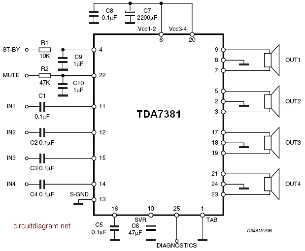
The amplifier is a quad amplifier circuit (amplifier with four inputs and four outputs) based on the TDA7381. This amplifier is designed for car audio systems, but it can also be utilized for other applications. The circuit has a...
Several years ago, National Semiconductor developed high-performance, user-friendly audio power amplifier circuits known as the LM3886. An additional amplifier was required to bi-amp homemade electrostatic speakers, prompting the selection of the LM3886 chip due to its ease of use,...
The following circuit illustrates the BUZ902DP 300 Watt Audio Power Amplifier Circuit Diagram. Features include audio frequency linearity from 20 Hz to 20 kHz. The BUZ902DP is a high-performance audio power amplifier designed to deliver up to 300 watts of...
These accessories are low-cost, high-speed, bifet-input operational amplifiers utilizing internally compensated voltage (BI-FET II technology). They require low supply voltages while offering a wide gain bandwidth product and fast slew rate. Additionally, well-matched high voltage JFET input devices accommodate...

This document illustrates the configuration of the high-precision, high-impedance OPA2111 amplifier. The total voltage circuit is designed for a magnification of Av = 10 (1 + 2R2 / R1), achieving a total gain of 1000 times. A gain stage...
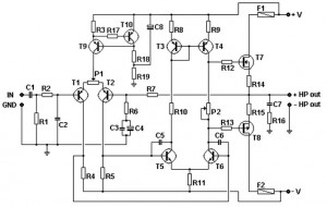
This basic MOSFET amplifier is simple to construct and low-cost, making it ideal for Hi-Fi amplifiers and instrument amplifiers such as guitars and keyboards. It delivers an output power of ±100 W RMS at an 8-ohm load or ±160...