
BUZ902DP 300 Watt Audio Power Amplifier
The BUZ902DP is a high-performance audio power amplifier designed to deliver up to 300 watts of output power. This circuit is particularly well-suited for high-fidelity audio applications, such as professional sound systems and home theater setups.
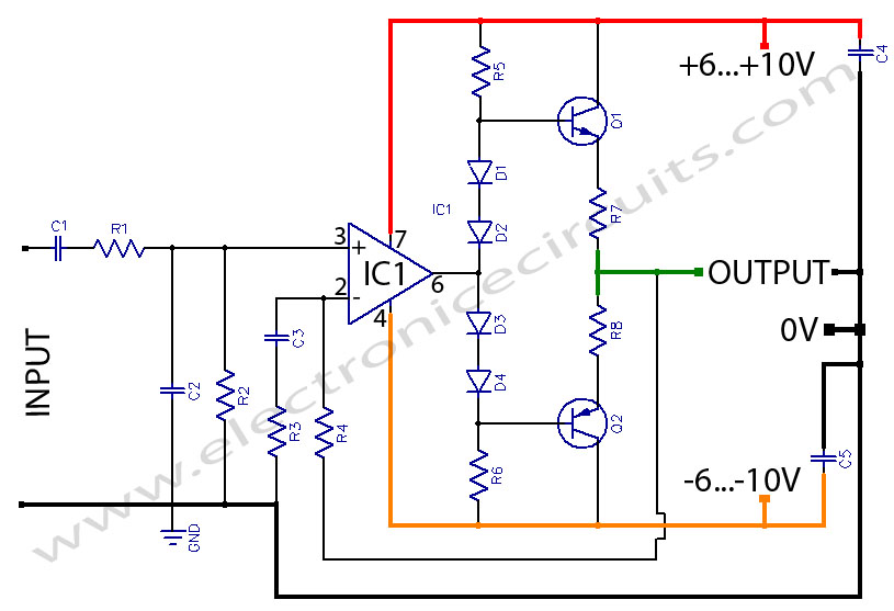
The circuit typically consists of several key components: the BUZ902DP power MOSFET, a power supply unit, input capacitors, feedback resistors, and output inductors. The power MOSFET is the central element that amplifies the input audio signal. The input section may include coupling capacitors that block any DC offset from the audio source, ensuring that only the AC audio signal is amplified.
The feedback network is crucial for maintaining audio frequency linearity. It helps stabilize the gain of the amplifier across the specified frequency range of 20 Hz to 20 kHz. This ensures that the audio output remains true to the original signal without distortion, providing a clear and accurate sound reproduction.
The output stage of the amplifier may include inductors that work to filter out unwanted high-frequency noise, further enhancing the sound quality. Additionally, proper heat dissipation mechanisms, such as heat sinks, are essential to manage the thermal performance of the BUZ902DP, especially at high power levels.
Overall, the BUZ902DP audio power amplifier circuit is designed to deliver robust performance while maintaining high fidelity, making it an excellent choice for audio enthusiasts and professionals alike.The following circuit shows about BUZ902DP 300 Watt Audio Power Amplifier Circuit Diagram. Features: 20 Hz 20 kHz Audio Frequency Linearity, .. 🔗 External reference
Related Circuits
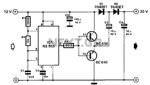
Using a 555 timer and voltage doubler, this circuit will supply over 50 mA at 20 V DC. Transistors T1 and T2 act as power amplifiers to drive the voltage doubler. The frequency of operation is approximately 8.5 kHz. The...

A simple lab power supply electronic project can be designed using this circuit diagram, which is based on the LM2576 monolithic integrated regulator that provides all the active functions for a step-down (buck) switching regulator. As seen in the...
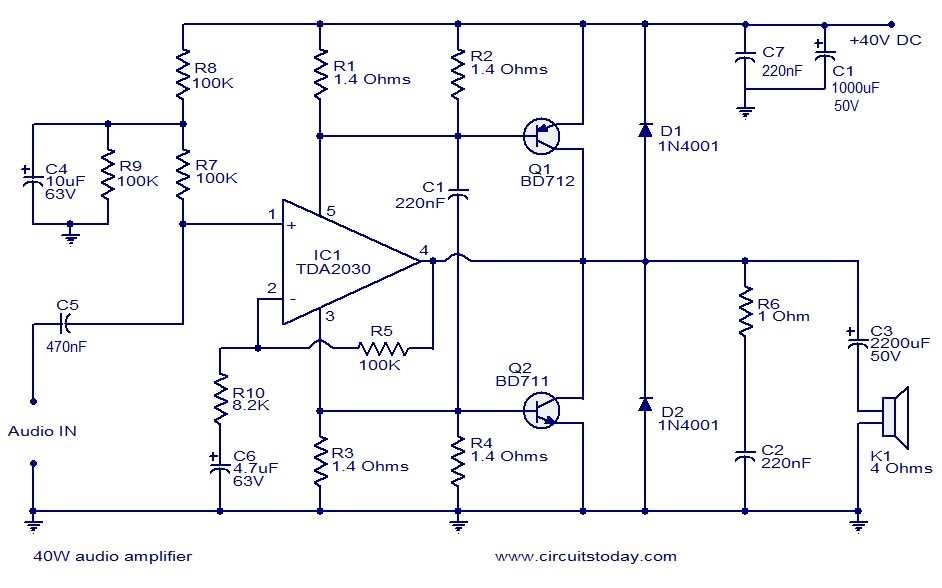
This is a highly effective 40W power amplifier design utilizing the TDA2030 integrated circuit and two transistors. The circuit consists of only a few components and does not necessitate a dual power supply. The input signal is connected to...
This circuit was designed and manufactured in the 1980s. Since then, it has operated without issues. There are no specific construction challenges, aside from the usual considerations: attention to the power supply requirements, selection of an appropriate heatsink, and...
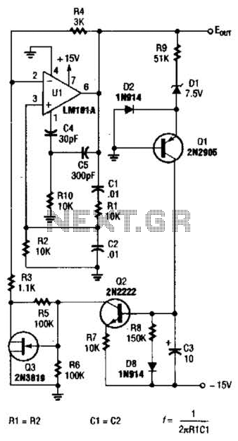
For variable-frequency operation, Rl and R2 can be replaced by a dual potentiometer. In electronic circuits that require variable-frequency operation, the use of a dual potentiometer as a replacement for resistors Rl and R2 can provide enhanced functionality and flexibility....
Headphone Amplifier or Pre-Amplifier Output Stage. This 1-watt amplifier is ideally suited for use as a driver for low-impedance headphones. The headphone amplifier circuit is designed to provide an amplified audio signal to drive low-impedance headphones effectively. Operating at a...