
100W AM Valve Transmitter circuit
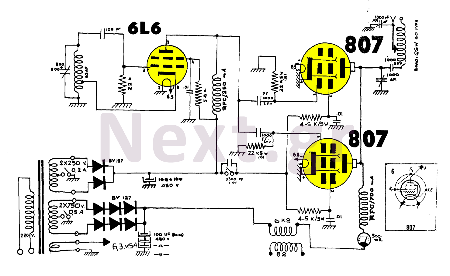
A 5.6 kΩ resistor is employed in series with the protective power supply at 300 volts to manage voltage drop (pin 4). An RF choke is installed on the anode to isolate the source without interfering with the high voltage current (pin 3). Coupling is facilitated by a 1000 pF capacitor and a 22 kΩ bias resistor on each side for the protective mesh feeding the 807 tubes (screen). A voltage drop is created with a 4.7 kΩ resistor from the 6L6 supply (300V).
In the high voltage sequence, a 0-500 mA meter is positioned before the RF anode choke (807) to allow for modulation rate control. The 100-watt transmitter operates vertically and is paired with a 35-watt (configurable) Duallex amplifier.
Upon completing the mechanical assembly, which includes positioning the transformer, electrolytic capacitors, switches, tube sockets, and various components, the electronic assembly begins. The output stage is mounted and tested, followed by the installation of any additional accessories.
Oscillation is initiated after selecting an empty frequency (typically between 1200-1500 kHz). The oscillation is fine-tuned to the desired frequency, ensuring harmonic stability. Once confirmed, the amplifier is closed, and the output is adjusted while monitoring the current to minimize mA. If two output variables are present, a combination of both resonances is utilized. After identifying the optimal tuning point (maximum sinking), the amplifier is gradually activated.
This circuit design exemplifies a well-structured approach to building a high-performance AM transmitter, ensuring efficient signal transmission and modulation capabilities.For our strong construction with the two 807 we do not need words. We all know the performance of such a machine. In this construction we have the peculiarity of high upward tension and independent coupling. On the output lamps, resulting in the output power being increased by several watts. We certainly will not talk about 130-150 watts, but we get 100 watts for sure. With an antenna of about 80 meters it can be heard at a distance of more than 100 kilometers.
The 6LB is a powerful oscillating lamp that may well drive the two 807 correctly, with an upward trend of 1050 VOLTS D.C. The oscillation is in a HARTLEY arrangement and is done with the oscillating coil of the 6SA7 block with a median take-off.
The coil for those who want to make it by themselves is from about 85 to about 85 coils. We cut its edge and we measure about 25 coils, take a medium shot and go to the 6L6 downhill 8, continue the winding, and at the end of about 85 spirals, we connect the variable oscillation that is grounding its edge. Continue taking a 100pF capacitor and go to the footplate 5. Here we polarize with a 22KΩ resistor.
With 5.6 KΩ we connect in series with the protective power supply from the 300 volts for voltage drop (foot 4).
We also install an RF chuck on the anode to "cut" the source, but this does not disturb the power supply with a high voltage current (leg 3) The coupling is done with a 1000pF capacitor and 22KΩ bias per side For feeding protective mesh On 807 (SCREEN) lamps we generate a voltage drop with a 4.7KΩ resistor from the supply of 6L6 (300V).

In sequence with the high voltage, before the RF anode chuck (807) we place a 0-500mA instrument and then the shaping blades to allow for a small modulation rate control. The 100 Watt transmitter is vertically upright with a 35 Watt (configurable) Duallex amplifier.
After we finish with all of the mechanical construction by placing the transformer on the edge, the electrolytic, the switches, the bases of the lamps, the bows, the variables, the worlds, the ammeter, and after all the mechanical logic ends, we start with the electronic part.
We mount the output stage and test it. Finally, we also mount any accessories,
We open the oscillation after we have chosen an empty frequency (usually between 1200-1500 kilocytes), we bring the oscillation to the frequency we want by watching it be an idol (harmonic), after making sure that it is correct and the amplifier closed, open the output and immediately with Variable output tune by passing the instrument to the less mA. "If there are two output variables, a combination of both resonances is made. After making sure that it is the best tuning point (the best sinking), open the amplifier slowly.
Related Circuits
The transmitter utilizes a 6BW6 vacuum tube to achieve an output power of approximately 5 watts. The circuit includes a component CI that is calibrated to produce the cleanest continuous wave (CW) note. The tuning capacitors C8 and C9...
The device is designed to accelerate the defrosting process of fish, meat, and other foods by utilizing audio vibrations. This method allows for defrosting in warm water, significantly reducing the time required compared to conventional methods, while preserving the...
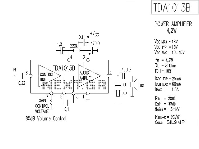
The following is a circuit for a 4-watt audio amplifier. The amplifier utilizes an integrated audio amplifier chip, TDA1013B, which is capable of delivering an audio power output of up to 4W at an 8-ohm load. Its wide supply...
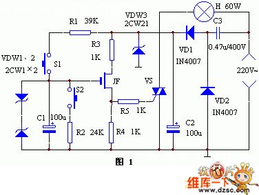
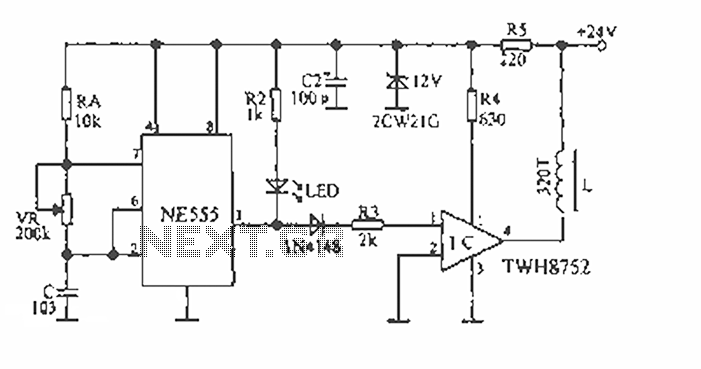
The keyer dimmer table lamp utilizes two touch buttons to adjust the light intensity. When one button is touched, the light dims from a strong brightness, while the other button increases the brightness from a dim state. The working...
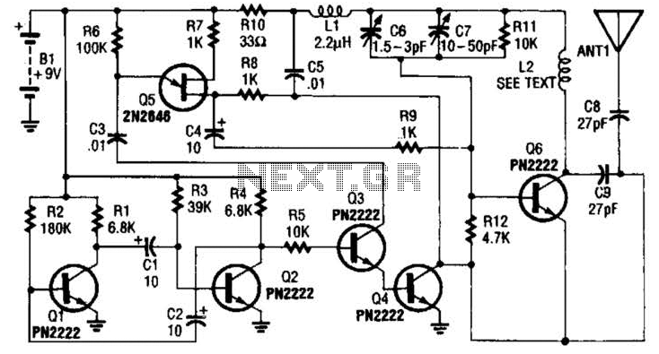
The 27MHz quartz crystal oscillator circuit is illustrated in figure 1. The biasing circuit consists of resistors R1, R2, and R3, while C6 serves as the bypass capacitor. The partial voltage circuit includes capacitors C1, C2, C3, and C4...
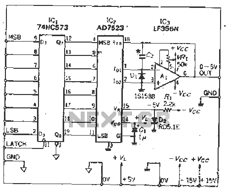
The IC latch is utilized to hold the digital data when the clock signal rises. The configuration includes a holding data port AD7s23, a thin film resistor ladder, and a switch that together form an 8-bit Digital-to-Analog Converter (DAC)....