
27MHz quartz crystal oscillator circuit
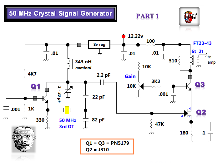
The 27MHz quartz crystal oscillator circuit is designed to generate a stable frequency output, utilizing a quartz crystal as its frequency-determining element. The circuit's biasing network, composed of resistors R1, R2, and R3, is essential for establishing the correct operating point of the active device, typically a transistor or operational amplifier. This configuration ensures that the oscillator operates within its linear region, allowing for consistent oscillation.
Capacitor C6 acts as a bypass capacitor, which helps to filter out high-frequency noise from the power supply, ensuring that the oscillator operates with minimal interference. The partial voltage circuit, comprising capacitors C1, C2, C3, and C4, is crucial for controlling the feedback within the oscillator. These capacitors allow for fine-tuning of the oscillation amplitude, which is vital for achieving the desired output signal strength without distortion.
The high-frequency choke coil L1 is integrated into the circuit to provide additional filtering. It prevents unwanted high-frequency signals from affecting the oscillator's performance, thereby improving the overall stability and purity of the generated frequency. The combination of these components facilitates the creation of a reliable 27MHz signal, which can be utilized in various applications, including radio transmission and frequency modulation systems.The 27MHz quartz crystal oscillator circuit is as shown in figure 1. The biasing circuit is composed of the R1, R2 and R3, C6 is the bypass capacitor. The partial voltage circuit is composed of the C1, C2, C3 and C4 to control the strength of oscillation. L1 is the high-frequency choke coil, it has the role of filtering. Figure 1 The 27MHz quartz crystal os.. 🔗 External reference
Related Circuits
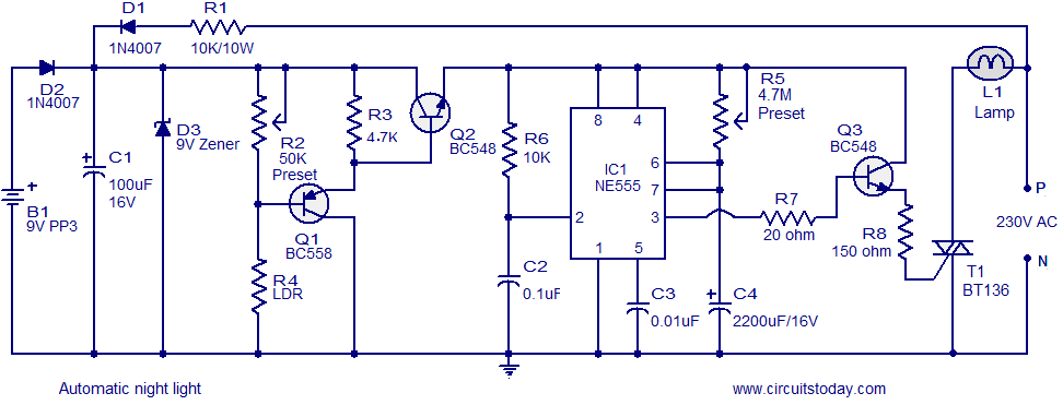
A simple and inexpensive automatic night light circuit designed using the timer IC NE555, which extinguishes after a preset time. This time can also be adjusted. The automatic night light circuit utilizes the NE555 timer IC configured in monostable mode....
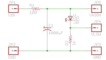
It is sufficient to explore PWM (Pulse Width Modulation) and digital-to-analog conversion, illustrating how to create a personal electronics workbench for investigating RC (Resistor-Capacitor) filters, charge and discharge curves, pulse generators, timers, and even a simple oscilloscope to understand...
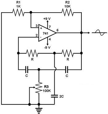
This circuit generates a sine wave using a single operational amplifier (741). The feedback loop of the op-amp includes a twin-T filter connected between its output and inverting input. Positive feedback for oscillation is provided by resistor R2. The...

The timer is activated by the zero-crossing voltage pulse. The time constant is defined by the combination of C5 and the resistors R14 and R15, which determines the conduction angle. The transistors T2 and T3 prevent the power switch...
The initial tasks involved acquiring VHF components and investigating the Butler crystal oscillator, particularly focusing on the common base variant. The VHF knowledge base is rich with established information. There are claims that the emitter follower variant of the...
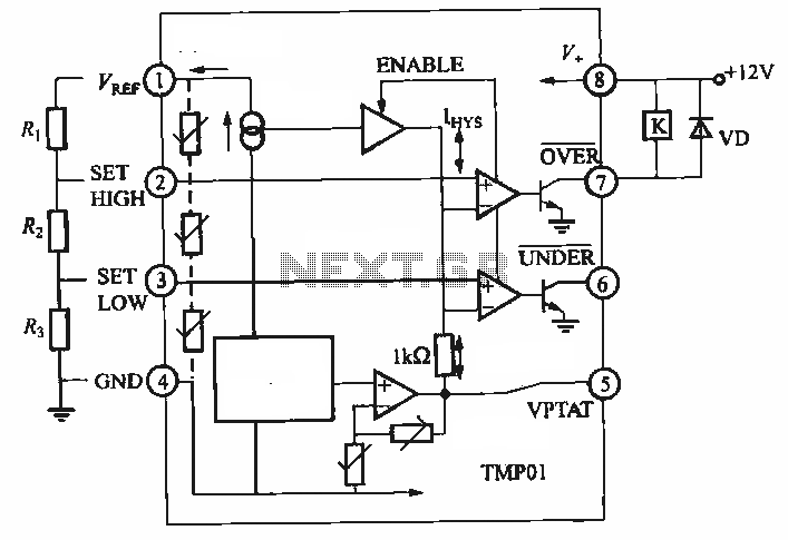
TMP01 is a temperature sensor that features a programmable temperature controller, an integrated reference voltage source, a current source, a voltage comparator, and an amplifier circuit. The internal circuit function block diagram and basic application circuit are provided. The key...
Warning: include(partials/cookie-banner.php): Failed to open stream: Permission denied in /var/www/html/nextgr/view-circuit.php on line 713
Warning: include(): Failed opening 'partials/cookie-banner.php' for inclusion (include_path='.:/usr/share/php') in /var/www/html/nextgr/view-circuit.php on line 713