
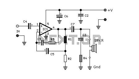
100W Class-A//AB Amplifier
The original simple 1969 JLH class-A design provided excellent first cycle accuracy through mid and high frequencies (dynamic clarity) because there were no stabilisation components nor a series output choke, whilst the NFB error correction was established via the input emitter (some describe this as current feedback). However, it did generate rather a lot of heat, the damping was soft at lower frequencies and the positive slew was weaker in the presence of loudspeaker system generated back-EMF at higher audio frequencies.
The Class A/Class AB amplifier circuit operates by utilizing a complementary push-pull configuration, which allows for efficient power delivery while minimizing distortion. The design typically incorporates bipolar junction transistors (BJTs) or metal-oxide-semiconductor field-effect transistors (MOSFETs) in the output stage, with the goal of achieving high linearity and low crossover distortion.
The circuit features a biasing network that ensures the transistors operate in Class A mode at lower signal levels, providing high fidelity and minimal signal distortion. As the input signal increases, the amplifier transitions into Class AB operation, allowing for greater efficiency and reduced heat generation during high power output scenarios.
Key components include the input stage, which may consist of a differential amplifier configuration to improve common-mode rejection and enhance signal integrity. Feedback is applied from the output to the input stage, often using a negative feedback loop to maintain linearity and control gain. The absence of stabilizing components in the original design contributed to its dynamic clarity, but modern iterations may incorporate additional elements to improve thermal stability and frequency response.
Thermal management is critical in this design, as Class A operation can lead to significant heat generation. Heat sinks are typically employed to dissipate excess heat, and thermal protection circuits may be included to prevent damage from overheating. Additionally, the design may utilize output capacitors to block DC offset and protect the loudspeakers from potential damage.
Overall, this amplifier design balances the benefits of Class A's audio fidelity with the efficiency of Class AB operation, making it suitable for high-performance audio applications while addressing previous limitations such as heat generation and frequency response.A Class A // Class AB amplifier rated 100 Watts when driving a 4 ohm loudspeaker. This circuit developed out of my 30+ years of JLH class-A based investigations. The original `simple` 1969 JLH class-A design provided excellent first cycle accuracy through mid and high frequencies (dynamic clarity) because there were no stabilisation components nor a series output choke, whilst the NFB error correction was established via the input emitter (some describe this as current feedback). However it did generate rather a lot of heat, the damping was `soft` at lower frequencies and the positive slew was weaker in the presence of loudspeaker system generated back-EMF at higher audio frequencies. I was eventually able to improve upo 🔗 External reference
Related Circuits
The circuit is designed to deliver approximately 10% distortion on a 4 Ohm to 8 Ohm loudspeaker. The LM4756 amplifier can output 7W of power. Utilizing four pairs of 2SC5200 and 2SA1943 transistors, this configuration can generate around 500W....
The EDFET drives like a FET, but with the bias stability of bipolar. Amps of output current can be controlled by milliamps of input current. The current gain is a design choice dictated by bandwidth. Two of things you...
This architecture allows for a wide tolerance in component selection, enabling the use of various components that may be readily available. The transistors utilized can be any NPN type power transistor, excluding Darlington configurations. The output power is approximately...
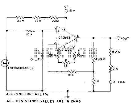
The circuit requires a 15-volt power supply and employs a precision operational amplifier, CA3193 BiMOS, to amplify the generated signal by more than 500 times. Three 22-megohm resistors are utilized to ensure a large-scale output in the event of...
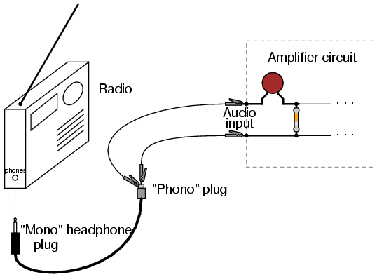
Where can one obtain a 12AX7 tube? These tubes are very popular for use in the preamplifier stages of many professional electric guitar amplifiers. A good music store will have them available for a modest price (around $12 US...
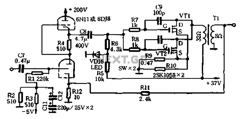
The amplifier circuit illustrated in Figure 2-25 features the following: (1) It utilizes a class 6N11 tube for parallel push-pull amplification, providing high-frequency response and an excellent signal-to-noise ratio. (2) The final stage of the semiconductor amplifier does not...