
Vacuum tube audio amplifier
This circuit design utilizes the 12AX7 vacuum tube in a preamplifier configuration, ideal for electric guitar amplifiers. The 12AX7 tube is a dual triode, which means it contains two independent amplifying sections within a single envelope. Each section can amplify audio signals, making it suitable for enhancing the sound of electric guitars by boosting the weak signals generated by the guitar's pickups.
The amplifier circuit should be constructed with careful attention to the power supply, which should provide approximately 170 volts DC to the plate of the vacuum tube. It is recommended to use a regulated power supply to maintain consistent voltage levels. The use of high-quality electrolytic capacitors in the power supply circuit is essential to ensure stability and reliability. The capacitors should be rated for a voltage significantly higher than 170 volts to accommodate any potential voltage spikes.
The audio input can be connected from a battery-powered device to the grid of the 12AX7 tube. Proper coupling capacitors should be used to block DC voltage while allowing AC audio signals to pass through. A common value for these coupling capacitors is around 0.1 µF, which effectively passes the audio frequencies while preventing any DC from the preceding stage from affecting the tube operation.
The ignition coil serves as an impedance-matching transformer, allowing the high-impedance output of the vacuum tube to drive a low-impedance speaker. The primary side of the ignition coil connects to the plate of the 12AX7, while the secondary side connects to the speaker. This setup allows for efficient transfer of audio power from the tube to the speaker, producing sound output.
Safety precautions must be strictly adhered to during construction and operation. All components should be rated for the voltages they will encounter, and proper insulation should be used to prevent accidental contact with high-voltage areas. Enclosures should be utilized to protect users from electrical shock and to safeguard the components from physical damage.
Overall, this circuit presents a fascinating exploration into vacuum tube technology and its applications in audio amplification, while also highlighting the importance of safety and proper component selection in high-voltage electronic designs.Where can you obtain a 12AX7 tube, you ask These tubes are very popular for use in the "preamplifier" stages of many professional electric guitar amplifiers. Go to any good music store and you will find them available for a modest price ($12 US or less). A Russian manufacturer named Sovtek makes these tubes new, so you need not rely on "New-Old-Stock" (NOS) components left over from defunct American manufacturers. This model of tube was very popular in its day, and may be found in old "tubed" electronic test equipment (oscilloscopes, oscillators), if you happen to have access to such equipment. However, I strongly suggest buying a tube new rather than taking chances with tubes salvaged from antique equipment.
It is important to select an electrolytic capacitor with sufficient working voltage (WVDC) to withstand the output of this amplifier`s power supply circuit (about 170 volts). I strongly recommend choosing a capacitor with a voltage rating well in excess of the expected operating voltage, so as to handle unexpected voltage surges or any other event that may tax the capacitor.
I purchased the Radio Shack electrolytic capacitor assortment (catalog # 272-802), and it happened to contain two 47 µF, 250 WVDC capacitors. If you are not as fortunate, you may build this circuit using five capacitors, each rated at 50 WVDC, to substitute for one 250 WVDC unit: Bear in mind that the total capacitance for this five-capacitor network will be 1/5, or 20%, of each capacitor`s value.
Also, to ensure even charging of capacitors in the network, be sure all capacitor values (in µF) and all resistor values are identical. An automotive ignition coil is a special-purpose high-voltage transformer used in car engines to produce tens of thousands of volts to "fire" the spark plugs.
In this experiment, it is used (very unconventionally, I might add!) as an impedance-matching transformer between the vacuum tube and an 8 © audio speaker. The specific choice of "coil" is not critical, so long as it is in good operating condition. Here is a photograph of the coil I used for this experiment: The audio speaker need not be extravagant.
I`ve used small "bookshelf" speakers, automotive (6"x9") speakers, as well as a large (100 watt) 3-way stereo speaker for this experiment, and they all work fine. Do not use a set of headphones under any circumstances, as the ignition coil does not provide electrical isolation between the 170 volts DC of the "plate" power supply and the speaker, thus elevating the speaker connections to that voltage with respect to ground.
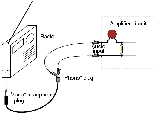
Since obviously placing wires on your head with high voltage to ground would be very hazardous, please do not use headphones! You will need some source of audio-frequency AC as an input signal to this amplifier circuit. I recommend a small battery-powered radio or musical keyboard, with an appropriate cable plugged into the "headphone" or "audio out" jack to convey the signal to your amplifier.
Welcome to the world of vacuum tube electronics! While not exactly an application of semiconductor technology (power supply rectifier excepted), this circuit is useful as an introduction to vacuum tube technology, and an interesting application for impedance-matching transformers. It should be noted that building and operating this circuit involves work with lethal voltages! You must exhibit the utmost care while working with this circuit, as 170 volts DC is capable of electrocuting you!
It is recommended that beginners seek qualified assistance (experienced electricians, electronics technicians, or engineers) if attempting to build this amplifier. WARNING: do not touch any wires or terminals while the amplifier circuit is energized! If you must make contact with the circuit at any point, turn off the "plate" power supply switch and wait for the filter capacitor to discharge below 30 volts before touching any part of the circuit.
If testing circuit vo 🔗 External reference
Related Circuits
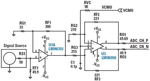
The LMH6703 is a wideband, DC-coupled monolithic operational amplifier specifically designed for ultra-high-resolution video systems. The LMH6703 operational amplifier is engineered to deliver exceptional performance in high-frequency applications, making it suitable for ultra-high-resolution video systems. It features a bandwidth of...
An operational amplifier designed for medium power applications, utilized as a headphone amplifier capable of driving low loads. The circuit consists of two amplifiers, with a voltage gain set at 40 dB, determined by the resistor pairs R3-R4 and...
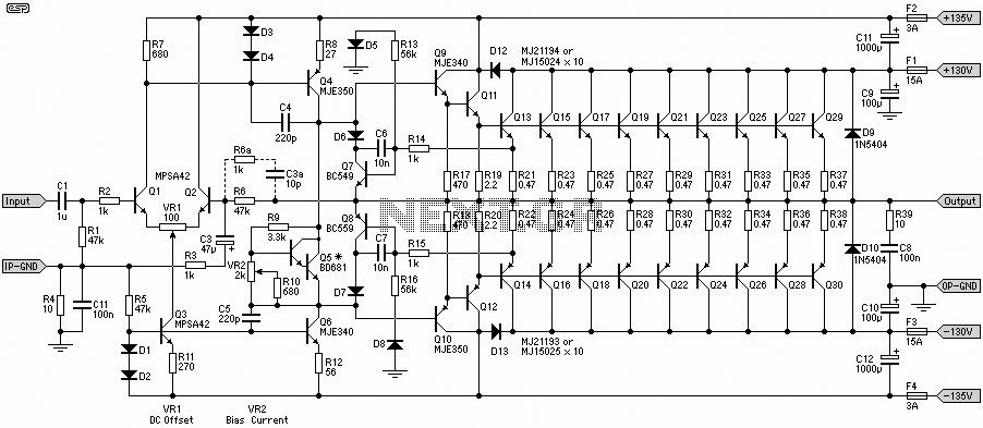
A 1500W power amplifier circuit design diagram created by Rod Elliott. The circuit utilizes 10 pairs of power transistors, specifically MJ15024 and MJ15025, or alternatively MJ21193 and MJ21194. The 1500W power amplifier circuit is designed for high-performance audio applications, providing...
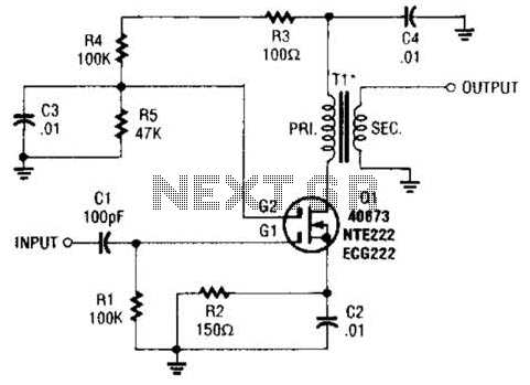
A MOSFET is utilized as a wideband buffer amplifier. T1 is wound on a toroid of approximately specified diameter, using material suitable for the frequency range, typically between 1 MHz and 20 MHz. The turns ratio should be approximately...
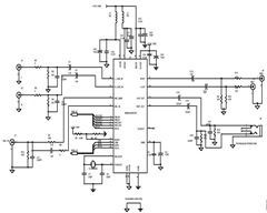
A typical circuit for applications such as mobile phones, MP3 players, and portable electronics utilizing the SSM2602 Low Power Audio Codec is provided in the SSM2602 Applications Circuit Schematic. The SSM2602 Low Power Audio Codec is designed for high-performance audio...
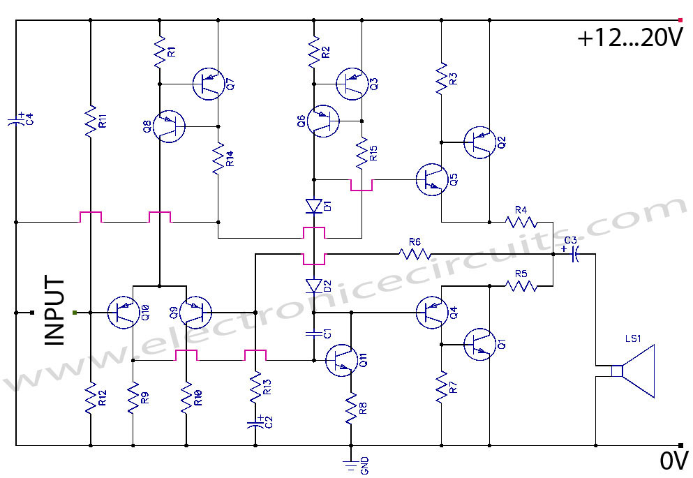
Discrete Class AB Transistor Audio Power Amplifier Circuit Diagram. This is a Class AB transistor power amplifier. It is a simple amplifier to... A Class AB transistor audio power amplifier is designed to provide high-quality amplification for audio signals while...