
With full power amplifier 01
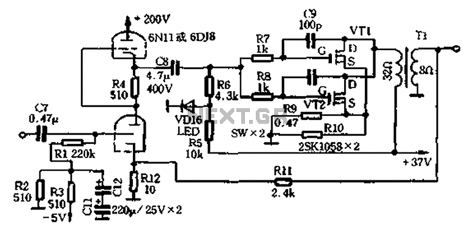
The amplifier circuit operates on the principles of parallel push-pull amplification, which enhances efficiency and linearity by allowing both halves of the waveform to be amplified simultaneously. The class 6N11 tube is particularly effective in this application due to its favorable characteristics, including a high transconductance and low distortion, making it suitable for high-frequency signal processing.
The lack of a regulated power supply in the final stage allows for a more straightforward design, although it may introduce some ripple in the output. The LC filter network, comprised of chokes and a substantial electrolytic capacitor, serves to smooth out voltage fluctuations, ensuring a stable output for the amplifier. The choice of a 20,000 µF capacitor is significant, as it provides ample energy storage to handle transient demands during operation.
The output transformer is a critical component in this amplifier design. The use of a laminated iron core minimizes eddy current losses, which is essential for maintaining efficiency, especially at higher frequencies. The winding configuration is carefully designed to optimize inductance and impedance matching, with the primary side having two windings of 100 turns each, allowing for flexibility in the design and potential adjustments during assembly.
In terms of construction, the use of different wire gauges for the windings enhances the robustness of the transformer. The 0.72mm wire provides a solid foundation for the primary winding, while the 1.02mm wire in the secondary winding ensures that the transformer can handle the required power levels without overheating. The triple-strand enveloping technique not only adds mechanical strength but also aids in reducing electromagnetic interference, thereby improving overall performance. Proper identification of the winding ends is crucial for ensuring correct phasing during assembly, which directly impacts the amplifier's efficiency and sound quality.Amplifier circuit shown in Figure 2-25. It has the following features: (1) promote the use of a class 6N11 tube for parallel push-pull amplification entire term, high-frequency response, a letter -to-noise ratio. (2) The final stage of the semiconductor amplifier tube amplifier does not use regulated power supply, can be seen from Figure 2 26, chokes and 20000r1F/50V electrolytic capacitor 1. SH/1. 5A composition LC filter network power (3 ) output transformer production easy, use of the tongue when homemade 24mm wide, 40mm thick laminated iron core made of high-quality silicon, early -stage total of 200 turns, the series consists of two 100 turns winding; a secondary with 100 turns, when the actual production with two 1) 0.
72mm and a root of 1. 02mm double wire high strength and stitch around three strands envelope, identify the head and tail of the three windings.
Related Circuits
When a short circuit to ground occurs, causing a DC voltage across the loudspeaker to be greater than or equal to V, an integrated protection circuit activates. This circuit limits the DC voltage across the loudspeaker to a value...
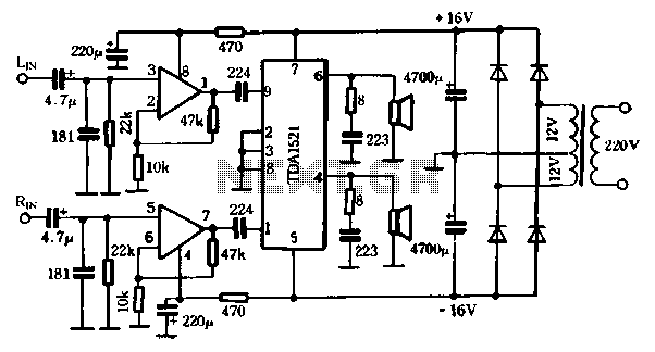
The first power amplifier circuit illustrated in Figure 5-88 utilizes the NE5532 operational amplifier, configured as a line amplifier, and features the TDA1521 power amplifier. This circuit operates with a dual power supply and eliminates the need for coupling...
The regulated output voltage fluctuated as the unregulated DC voltage changed, which in turn varied with the load current or the incoming AC line voltage. There was no straightforward solution to the existing circuit that would rectify this issue....
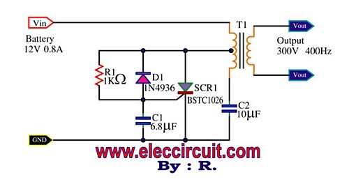
This is a Mini Power Inverter that utilizes SCR as the main electronic component. It operates an oscillator generator at 400Hz, providing an output of 300V from a 12V input voltage. The Mini Power Inverter is designed to convert a...
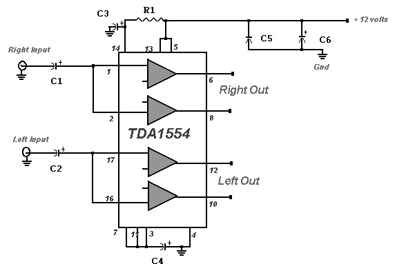
A 22 Watt stereo amplifier circuit diagram is presented. This circuit can be utilized for audio home amplifiers as well as car audio amplifiers. It features a straightforward design, is cost-effective, and is very easy to assemble, making it...
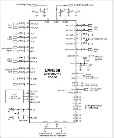
The LM4610 is a DC-controlled tone (bass/treble), volume, and balance circuit designed for stereo applications in car radios, televisions, and audio systems. It also incorporates National's 3D-Sound circuitry, which can be adjusted externally using a simple RC network. An...