
100W FET audio amplifier

The balanced preamplifier circuit serves to enhance the quality of audio signals by reducing noise and interference, making it ideal for professional audio applications. The circuit typically incorporates operational amplifiers (op-amps) configured in a differential mode to achieve the desired amplification while maintaining a balanced signal path.
The input stage of the preamplifier accepts balanced audio signals, often from sources such as microphones or musical instruments. The balanced configuration helps to cancel out common-mode noise, which is particularly beneficial in environments with significant electromagnetic interference. The op-amps are selected based on their low noise characteristics and high input impedance to ensure minimal loading on the audio source.
The output stage of the circuit also maintains a balanced signal, allowing for compatibility with other audio equipment, such as mixers and amplifiers. This design not only improves signal integrity but also enables longer cable runs without degradation of audio quality.
Power supply considerations are critical for the operation of the preamplifier. Typically, a dual power supply (positive and negative voltages) is used to provide the necessary headroom for the op-amps, ensuring that the output signal remains linear and distortion-free across the intended range of operation.
In summary, this balanced preamplifier circuit is a robust solution for amplifying low-level audio signals while preserving signal integrity and reducing noise, making it an essential component in high-fidelity audio systems.This Balanced pre amp circuit is designed to amplify a little line-level audio signal (from 0 dB to 20 dB), and has balanced inputs and outputs. The scheme uses only conventional components, you`ll have no trouble finding in any electronics. 🔗 External reference
Related Circuits
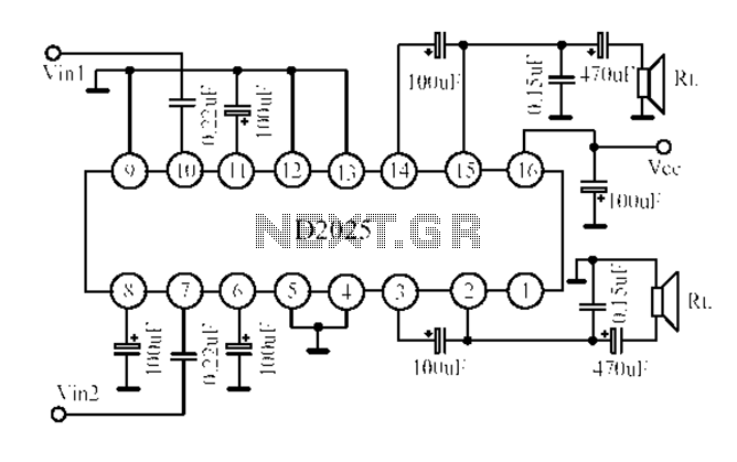
The D2025 is a dual audio power amplifier circuit designed as a stereo audio power amplifier integrated circuit. It comes in a DIP16 package and is applicable for various portable devices, such as tape recorders or portable stereo systems....
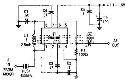
Up to 60 dB of gain at 455 kHz is available with the MC1350P. RES1 is a ceramic resonator, LC, or crystal filter. Keep the leads to pins 1, 2, 3, and 7 short. The MC1350P is a versatile integrated...
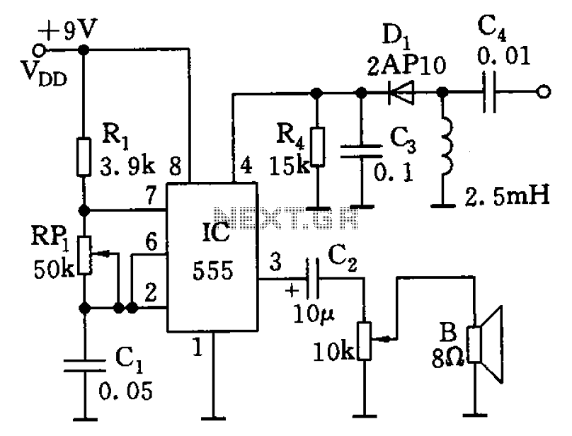
The circuit features a 555 timer along with resistors R1, RP1, and capacitor C1, functioning as a controllable audio oscillator. The frequency of the oscillator is determined by the formula f = 1.44 / ((R1 + 2 * RP1)...
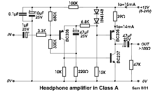
Even if simple, the circuit meets all conditions regarding distortion and frequency response. The input resistance is 250K ohms, and it can drive loads between 100 ohms and 2K ohms. The described circuit is a basic signal processing circuit designed...
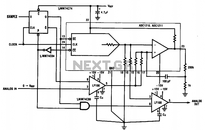
During normal hold mode, the replicated analog voltage is buffered directly through the sample-and-hold (S/H) amplifier to the output. Upon receiving a SAMPLE signal, the S/H amplifier enters hold mode, maintaining the voltage until the new analog voltage is...
%2B2%2BCH%2Bby%2BIC%2B%2BNE5532%2Bor%2BLF353.jpg)
This is a microphone preamplifier circuit model 2 CH. The circuit utilizes integrated circuits NE5532 or LF353 to amplify the sound signal from a dynamic microphone, increasing the power level for subsequent input into a stereo power amplifier. This...