
100W Inverter Circuit 12VDC to 220VAC
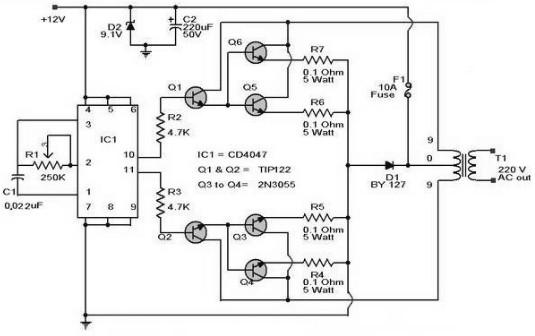
The 100W inverter circuit is designed to efficiently convert a low-voltage DC input into a standard AC output suitable for powering household appliances. The core component of this inverter is the CD4047 integrated circuit, which functions as an oscillator. It generates a 50Hz sine wave signal, which is essential for mimicking the utility power supply frequency.
The generated sine wave signal is then fed into a power transistor, specifically the 2N3055. This transistor operates in the linear region, allowing it to amplify the current of the sine wave signal. The 2N3055 is capable of handling high currents, making it an ideal choice for applications requiring substantial power output.
Following the amplification, the signal is directed to a transformer. The transformer plays a crucial role in stepping up the voltage from the low DC input level to the desired high AC output voltage of 220V. The turns ratio of the transformer is selected based on the input and output voltage requirements, ensuring that the output waveform remains as close to a pure sine wave as possible.
In addition to these components, the circuit may include various passive components such as resistors and capacitors for signal conditioning, as well as protective elements like diodes to prevent back EMF from damaging the circuit during operation. Proper heat dissipation measures should also be implemented for the 2N3055 transistor, as it can generate significant heat under load. Overall, this inverter circuit is a practical solution for converting DC power to AC power for use in various applications.Here the schematic diagram of 100W Inverter Circuit which will convert 12VDC input to be 220VAC output. The circuit built based IC CD4047 to generate sine wave signal 50Hz and then the power transistor 2N3055 will boost the signal so that the signal have high power (high electric current).
Then the sine wave signal will be stepped up by the transf ormer. 🔗 External reference
Related Circuits
This is a less polished version of Handmade Electronic Music, featuring nearly identical content and available for free. Notably, refer to Chapters 18 and 20. The layout consists of conductive metal strips beneath the perforations of the breadboard. Typically,...
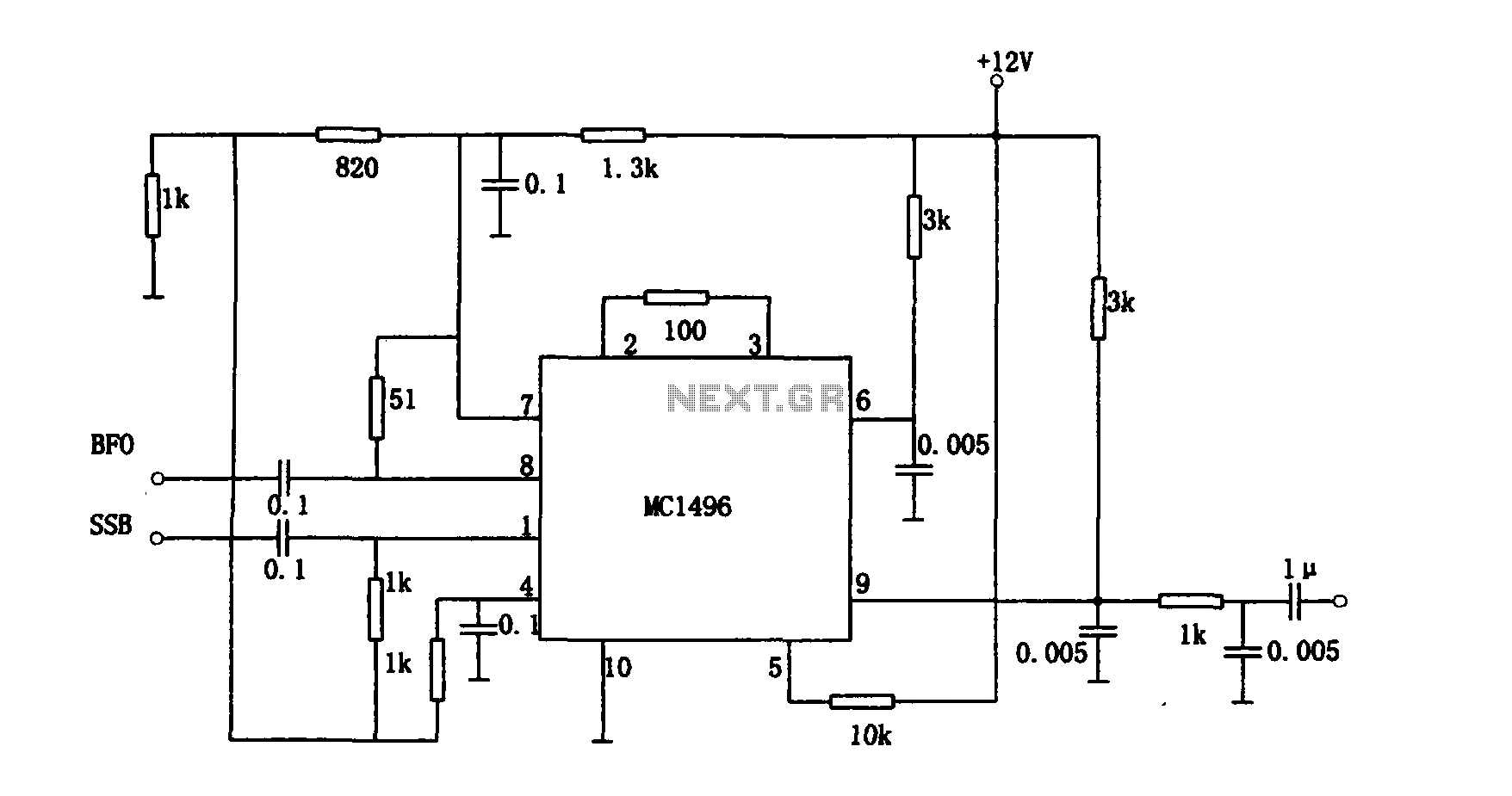
The provided information pertains to a detector circuit designed for multiplication. This circuit functions as a single-sideband amplitude modulation (SSB AM) signal detector, utilizing its principles to demodulate the received single-sideband signal and recover the transmitted signal. It employs...
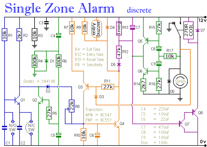
The circuit includes automatic entry and exit delays, a timed bell cut-off, and a system reset feature. It accommodates both normally open and normally closed switches, making it compatible with common input devices such as pressure mats, magnetic reed...
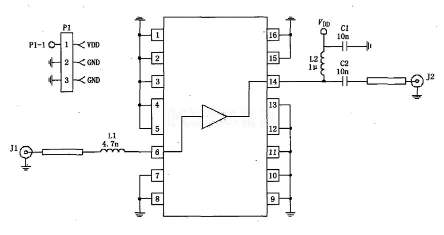
A 50-ohm impedance is illustrated in the RF2320 linear amplifier circuit, which is configured for input and output using transmission lines and inductive or capacitive components to create a matching network. The RF2320 linear amplifier circuit is designed to operate...
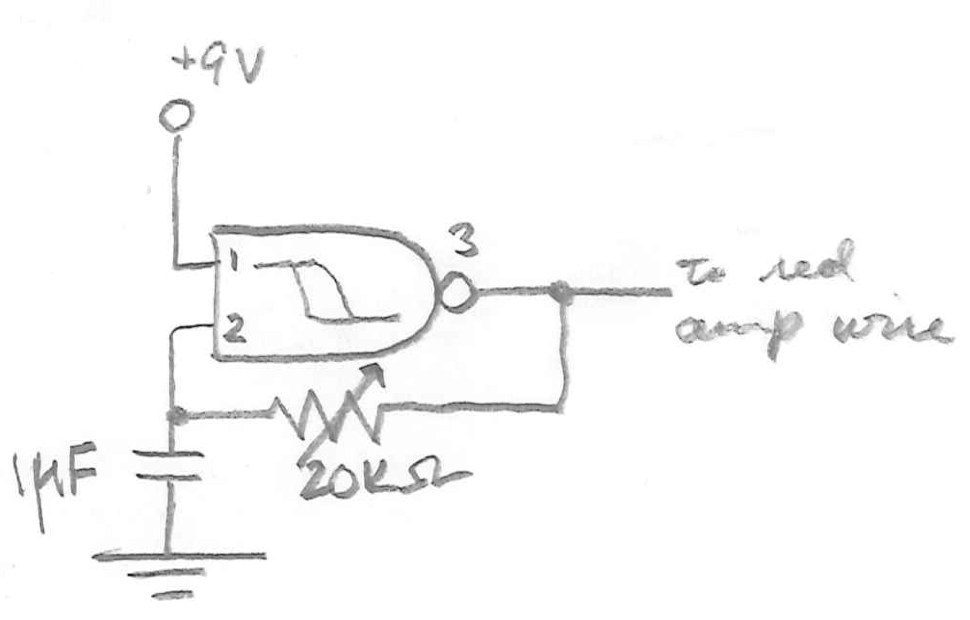
Automatic Gain Control (AGC) is a circuit design that maintains a consistent level of amplification for sound or radio frequency signals. If the signal is too low, the AGC increases the gain to ensure the output remains at a...
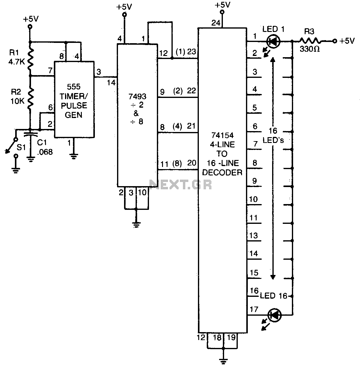
The 555 timer generates a rapid series of pulses when switch SI is in the open position. These pulses are grouped into sets of 16 and converted into binary format by the 7493 counter. The binary output is then...
Warning: include(partials/cookie-banner.php): Failed to open stream: Permission denied in /var/www/html/nextgr/view-circuit.php on line 713
Warning: include(): Failed opening 'partials/cookie-banner.php' for inclusion (include_path='.:/usr/share/php') in /var/www/html/nextgr/view-circuit.php on line 713