
Multiplication detector circuit with MC1496
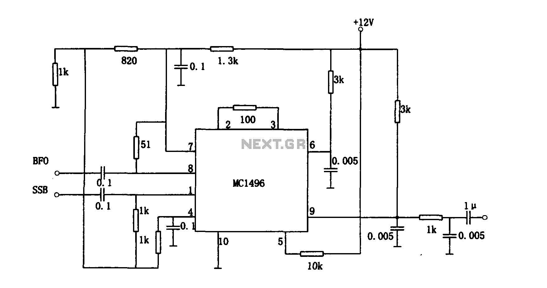
The circuit operates by utilizing the MC1496, which is a versatile integrated circuit designed for balanced modulation and demodulation applications. In this configuration, the MC1496 serves as both the modulator and demodulator, effectively handling the SSB signal. The input to the circuit consists of the SSB signal alongside a carrier frequency, which is essential for the demodulation process.
The principle of operation involves the multiplication of the incoming SSB signal with the carrier signal. This multiplication process results in the extraction of the original baseband signal from the modulated carrier. The output voltage is directly proportional to the product of these two signals, which is critical for recovering the transmitted information.
The circuit's intermediate frequency sensitivity of 9 MHz indicates its operational bandwidth, allowing it to process signals within this frequency range effectively. A sensitivity of 3 µV showcases the circuit's ability to detect weak signals, making it suitable for applications where signal strength may be a concern. Additionally, the dynamic range of 90 dB demonstrates the circuit's capability to handle a wide range of signal amplitudes, ensuring reliable performance in various operating conditions.
In summary, this detector circuit is a sophisticated solution for demodulating SSB signals, leveraging the MC1496 to achieve high sensitivity and a broad dynamic range, thereby facilitating effective communication in radio frequency applications.As shown for the detector circuit multiplication. The circuit is a single-sideband amplitude modulation signal detector, its principle is to demodulate the received single sideband (SSB) and the receiver to recover the signal transmission carrier multiplying demodulation completion work. FIG manifold MC1496 balanced modulator and demodulator, the output voltage of the circuit is the product of the input voltage signal provided by the carrier and switch function. The circuit operates at an intermediate frequency sensitivity 9MHz 3 mu V, a dynamic range of 90dB.
Related Circuits
In appliances that require alternating current, NiCad (NiCd) rechargeable batteries still demonstrate significant performance advantages compared to NiMH and lithium batteries. The charger circuit is critical in handling incorrect polarity of the battery placement. The core of this battery...
The time is set by potentiometer R2, which provides a range from 1 second to 100 seconds, using a timing capacitor C1 of 100 µF. The output at pin 3 is normally low, keeping the relay in the off...
Full sine wave UPS information in English, along with detailed C language source code. English proficiency may be a concern, so caution is advised. A full sine wave Uninterruptible Power Supply (UPS) is designed to provide a stable and continuous...
This is a simple game show timer designed for beginners. The power source can be a standard 12-volt lantern battery or a battery pack made from C or D cells. The lamps used can be regular flashlight bulbs; the...

In this circuit, an additional exclusive-OR gate is connected after the modulo-2 feedback, with CI and R2 applying the supply turn-on ramp into the feedback loop. This provides sufficient transient signal so that the PRBS generator can self-start during...
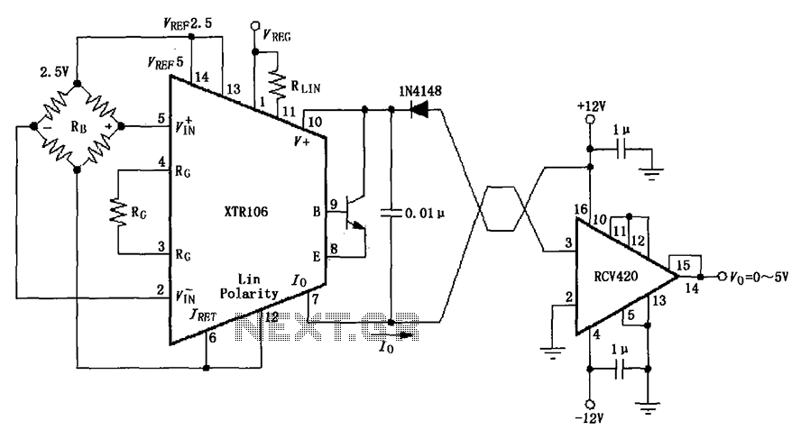
The IN4148 series diode is connected in the V+ line and configured in a loop to prevent damage from reverse voltage conditions. The diode exhibits a forward voltage drop of approximately 0.7V, which affects the supply voltage. The circuit...