
100w inverter circuit schematic
The 100 Watt inverter circuit is designed to convert direct current (DC) into alternating current (AC) with a power output of 100 Watts. The core component, the CD 4047 IC, serves as the pulse generator. In this configuration, the IC operates in astable mode, which allows it to continuously produce square wave signals. The frequency of these signals is determined by the external resistor and capacitor values connected to the IC.
The output from the CD 4047 is fed into the bases of four 2N3055 transistors, which are configured in a push-pull arrangement. This configuration allows for efficient driving of the load by switching the transistors alternately, thereby creating an AC waveform. The 2N3055 transistors are capable of handling high current loads, making them suitable for this application.
To ensure proper operation, the circuit includes necessary components such as resistors and capacitors for biasing and stabilization. Additionally, a transformer may be used at the output stage to step up the voltage to the desired level for the AC output. The entire circuit is designed to be compact and efficient, making it suitable for various applications where a reliable inverter is required.
Safety features should also be considered, such as fuses or circuit breakers, to protect against overload situations. Overall, this inverter circuit provides a straightforward solution for converting DC to AC power with minimal components while maintaining functionality and efficiency.Here is a 100 Watt inverter circuit using minimum number of components. Here we use CD 4047 IC from Texas Instruments for generating the 100 Hz pulses and four 2N3055 transistors for driving the load. The IC1 Cd4047 wired as an astable multivibrator produces two 180 degree out of phase 100 Hz pulse trains..
🔗 External reference
Related Circuits
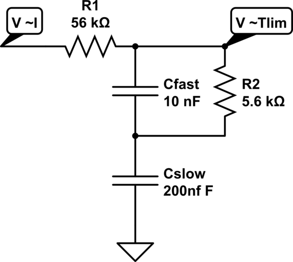
A MOSFET is employed to drive a load that includes a sense resistor in its current path. The voltage across this resistor is utilized to trigger a circuit capable of disconnecting the load in the event of an overcurrent...
The schematic represents a water level alarm circuit. This circuit functions as a water level sensor and emits a melodious alarm sound when the two probes within the circuit detect the presence of water. This water level indicator circuit...
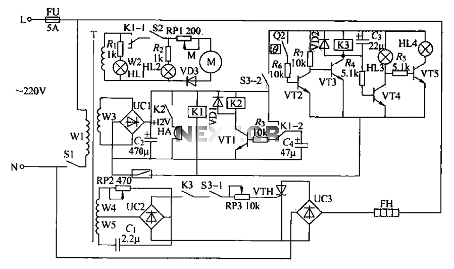
A chemical mixer circuit equipped with stirring speed control, a thermostat, and a timer alarm function is suitable for use in the chemical, steel, and other industries. The circuit includes components for heating, magnetic stirring, motor control, and timing...
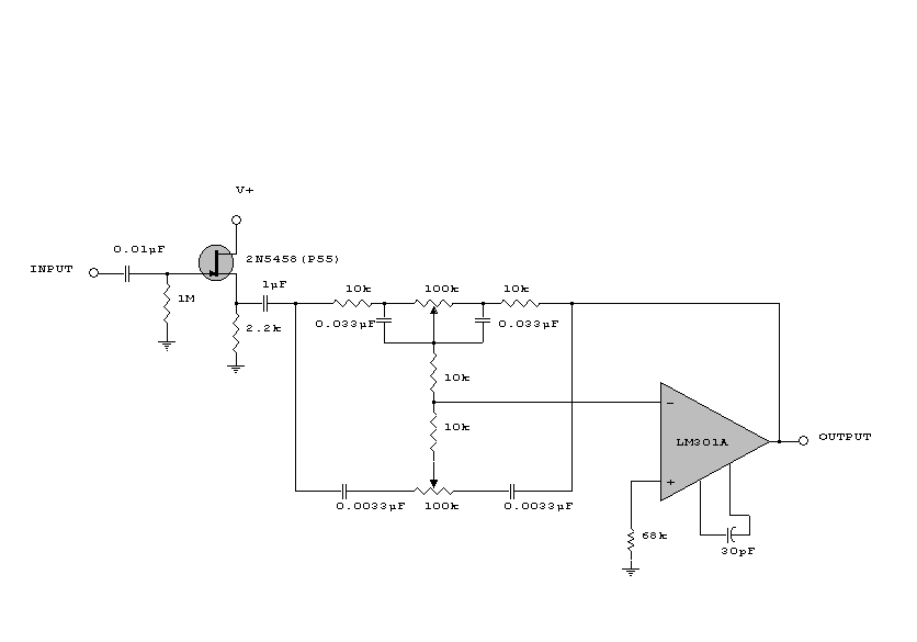
This circuit is a simple series tone control circuit. It utilizes the surgical amplifier LM301A. The JFET 2N3684 provides high input impedance and low noise for the unbuffered operational amplifier, which operates in an equalizer (EQ) configuration. Further details...
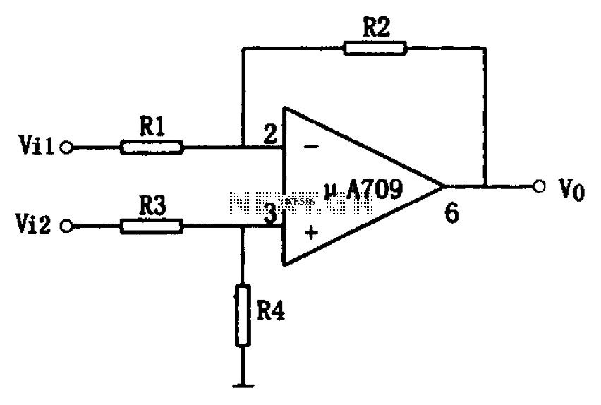
The simple differential amplifier circuit consists of two input signals, Vi1 and Vi2, which are connected through resistors R1, R3, and R4, forming a voltage divider circuit at the op-amp input. Vi1 is applied to the inverting input of...
All electronic circuits were initially built on breadboards. Once the circuits were operational, they were soldered onto perfboards to create a more durable system. A power board was designed to stack two batteries in series, providing access to a...