
op amp Detect real overcurrent/short-circuits vs. current peaks
A circuit utilizing a MOSFET to drive a load with a current sense resistor involves several critical components and considerations. The MOSFET serves as a switch, controlling the power delivered to the load based on the current flowing through the sense resistor. The voltage drop across the sense resistor is proportional to the load current, which is monitored to detect overcurrent conditions.
In this configuration, the sense resistor is placed in series with the load, and its voltage is fed into a comparator circuit or an operational amplifier configured as an integrator. This integrator can provide an output that represents the integral of the current over time, effectively measuring the product of current and duration. By integrating the current, the circuit can distinguish between short-duration current spikes and sustained overcurrent conditions.
The output of the integrator can be fed into a latch circuit, which will activate when a predetermined threshold is crossed, indicating that the current has exceeded safe levels for too long. This design approach mitigates the risk of false triggering caused by transient pulses from the load. The choice of components, such as the operational amplifier, must ensure that it can handle the expected current levels and provide a fast enough response time to engage the MOSFET before damage occurs.
In addition to the primary components, it may be beneficial to include filtering capacitors to smooth out transient signals and protect the circuit from noise. A feedback mechanism could also be integrated to adjust the sensitivity of the circuit to different load conditions, allowing for greater flexibility in operation.
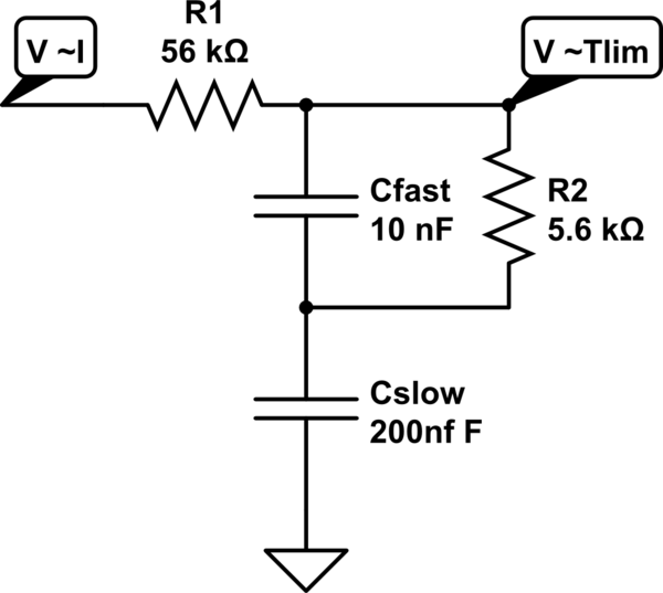
Overall, this circuit design addresses the complexities associated with overcurrent detection in a load with dynamic characteristics, providing a reliable solution to protect the MOSFET and associated circuitry from damage. Further research into industry standards and best practices may yield additional insights into optimizing the design for specific applications.A MOSFET that drives a load. The load has a sense resistor in its current path and its voltage is used to trigger a circuit that can disconnect the load if we detect an over current condition. But it wasn`t that easy. Many kinds of loads generate large pulses when connected (input capacitors, etc), so temporal overcurrents can actually trigger the latch, so we fed
that current sense voltage into a capacitor. It looks like this: The issue is that higher currents will kill the MOSFET (and other existing circuitry) exponentially faster, while higher voltages (from the current sense) will change the capacitor less than linearly faster. If we tweak the value for a reasonable current/time to trigger the latch, a higher current will take too long, while tuning for a high current will overshoot at lower currents.
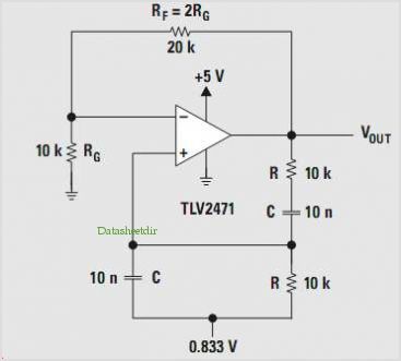
We have been thinking about using a thermistor instead of a capacitor (right response curve) but they all seem to be too slow for our case (at 200A we have about 40us to shut off). Now there`s an idea of using an integrator op-amp to measure current*time. Does any of that make sense Is there a industry standard practice for this sort of case This can`t really be this complicated, it feels like it should be a common issue.
can it Isn`t it :) Our issue is not about the components (whether the op-amp will be able to drive the MOSFET at X Amps), it is about triggering in `this is too high too long` rather than on `high current but short and okay` situations. I`ve removed the device names accordingly :) 🔗 External reference
Related Circuits
The HV732 is a complete, high-speed, high-voltage ultrasound transmitter pulser. This high-performance CMOS integrated circuit (IC) is housed in a single 7x7x0.9 mm 44-lead multi-die QFN package. The HV732 can deliver up to ±2A source and sink current to...
This circuit serves as a dependable alternative to thermally-activated switches designed for flashing Christmas tree lamps. The arrangement consisting of Q1, Q2, and associated resistors activates the silicon-controlled rectifier (SCR). The timing function is determined by resistors R1, R2,...
This is a simple microphone preamplifier circuit which you can use between your microphone and stereo amplifier. This circuit amplifier microphone suitable for use with normal home stereo amplifier line/CD/aux/tape inputs. This microphone preamplifier can take both dynamic and...
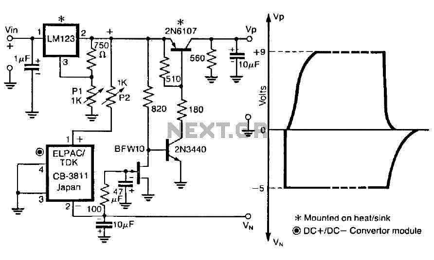
The control circuit is designed to operate by doubling a positive supply, which activates the first door when powered on and deactivates when the first drain is engaged, as illustrated in the accompanying figure. This circuit incorporates the LM123,...
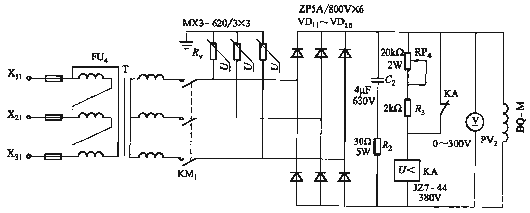
FIG T is the excitation transformer, R is a varistor, and there are rectifier diodes to protect against breakdowns from VDii to VD16; Rz and C2 provide resistive-capacitive protection. The circuit is designed to absorb voltage from the magnetic...
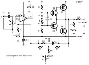
This audio amplifier circuit is based on the operational amplifier NE5532 and utilizes a pair of power transistors, TIP41A and TIP42A. It is capable of delivering up to 10W of audio power output into an 8-ohm speaker. The design...