
sensors circuits
The electronic circuit described operates effectively within a robust framework designed for reliability and efficiency. The initial use of breadboards allows for rapid prototyping and testing of circuit functionalities, while the transition to perfboards solidifies the design for practical applications. The power board configuration, which stacks batteries, ensures that the system can operate on two distinct voltage levels, enhancing versatility in powering various components.
The separation of high power electronics from logic circuits is a critical design choice that mitigates the risk of electromagnetic interference, which could lead to erratic behavior in sensitive logic components. The integration of an emergency stop feature is a vital safety measure, providing a fail-safe mechanism that ensures the system can be quickly deactivated without compromising the operational state of the logic circuits.
The voltage regulation circuit is particularly noteworthy, as it utilizes a low dropout regulator to maintain functionality even under low battery conditions. This feature is essential for applications where battery life is a concern, ensuring that the logic circuits receive stable power until the battery is critically low. The flash sensor and tape sensor demonstrate the circuit's ability to interact with environmental stimuli, allowing for dynamic responses based on visual cues.
The ball color sensor enhances the system's capability to differentiate between various objects, enabling more complex interactions and operations. The high-power H-Bridge is an efficient solution for motor control, allowing for precise speed regulation and direction changes through PWM. The design's consideration of average power dissipation and the choice of a cost-effective voltage regulator reflect a balanced approach to performance and cost-efficiency, making this circuit suitable for a range of applications in robotics and automation.All of our electronic circuits were originally constructed on breadboards. Once the circuits were working, we soldered them on perfboards to give us a more robust system. We created a power board which stacked two batteries in series. This gave us access to a 14. 4V line and a 7. 2V line. We separated our high power electronics from all of our logic circuits to decrease the potential for noise. We also implemented an emergency-stop which cut power to the actuators but left the logic circuits running. This allowed us to stop all of our motors if something went wrong but keep the logic circuits running.
This board contains 4 primary elements. The first is the voltage regulating circuit. We used a low dropout regulator to power this board from a single battery. This means that the logic circuit could be powered even if the battery voltage dropped as low as 5. 5V. The second element is the flash sensor. We used a comparator connected to an NPN phototransistor to detect a camera flash. The third element is the tape sensor. We used an IR emitter coupled with an IR phototransistor to detect when we were on a particular color of tape. The output of the circuit fed into an A/D port and we calibrated the reading to determine tape color.
The final element is the ball color sensor. It uses an IR emitter and detector to determine whether we obtained a black ball, a yellow ball, or no ball. We used a high power H-Bridge to control our launcher motor with PWM in drive-brake mode. We voltage regulated the launcher so that its speed would be independent of battery voltage. The voltage regulator sees a large amount of current for brief periods of time but once the wheel is spinning, the current draw is low.
Thus, the average power dissipation is low and we were able to use a cheaper voltage regulator (L7805) instead of a very high current regulator. 🔗 External reference
Related Circuits
This page provides basic information about voltage comparator integrated circuits and is to act as reference material for other circuits. The circuits shown are based on the LM339 Quad Voltage Comparator chip or the LM393 Dual Voltage Comparator chip....
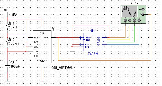
This tutorial explores a common digital concept using the NI Multisim software environment. It examines a four-bit counter that uses a 555 timer IC to generate the clock signal. This tutorial takes less than 30 minutes to complete and...
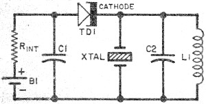
Leo Esaki invented the tunnel diode in 1957 while working at Sony (then known as Tokyo Tsushin Kogyo). Tunnel diodes feature a very narrow, heavily doped p-n junction approximately 10 nm wide, which exhibits a broken bandgap. This configuration...
This weblog focuses on electronic circuit schematics, PCB design, DIY kits, and diagrams for various electronic projects. It features a mixer that demonstrates how to create microphone pre-amplifiers suitable for both low and high impedance microphones. The design utilizes...
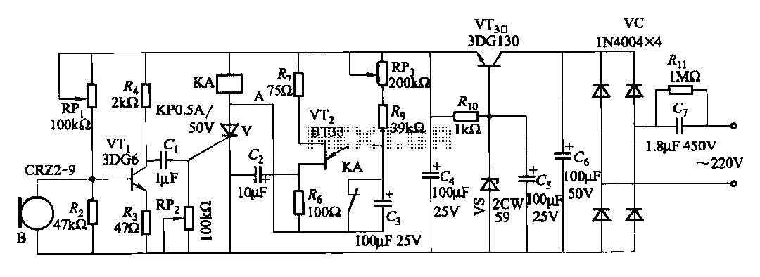
The circuit features voice switches with Figure 2109. It utilizes a single-junction transistor (VT2) and RC components to create a delay. The delay time can be adjusted using the potentiometer (RP3) or the capacitor (C3). The described circuit employs a...
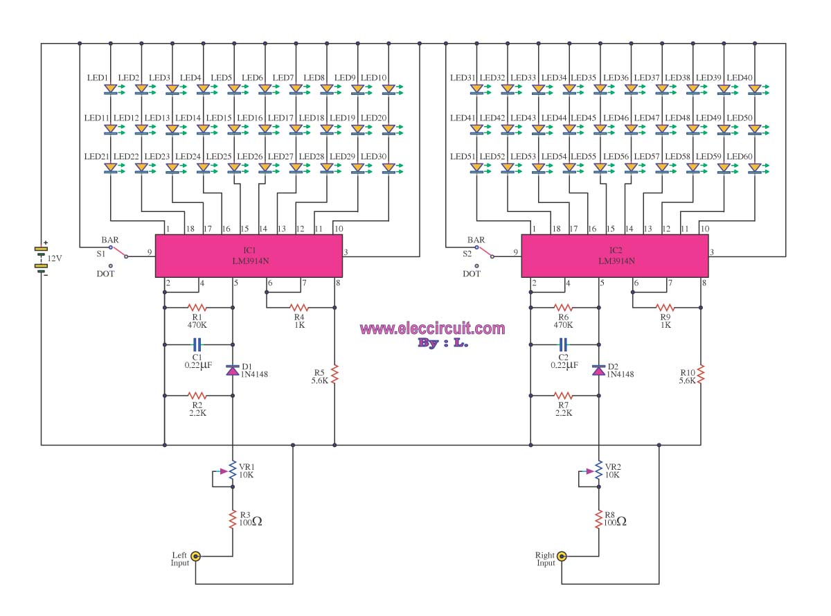
A VU meter is utilized to display the power level of audio signals and also serves as an aesthetic element. When purchasing a VU meter kit from an electronics store, options include assembling various parts independently or selecting a...