
10Khz oscillator
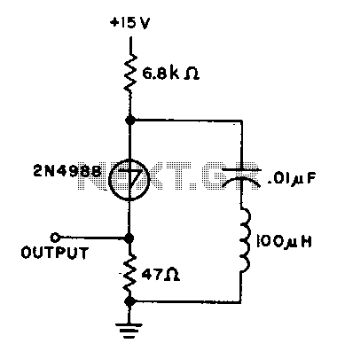
In this circuit, the operation begins with the capacitor charging to a predetermined switching voltage. This voltage is critical as it determines when the switch (SUS) will activate. Upon reaching this voltage threshold, the SUS switch closes, allowing current to flow through the inductor. The inductor, due to its property of opposing changes in current, causes the current to oscillate or "ring." This oscillation is a result of the energy stored in the inductor being released and then reabsorbed in the circuit.
As the current continues to flow, it eventually decreases. The point at which this current falls below a specific value known as the holding current is essential for the operation of the circuit. Once this threshold is crossed, the SUS switch turns off, interrupting the current flow. This cessation of current causes the capacitor to begin charging again, thus restarting the cycle.
This repeating cycle of charging, switching, and discharging is fundamental in various applications, such as in power converters or oscillators, where controlled energy transfer is necessary. The precise values of the capacitor, inductor, and the defined switching and holding currents are crucial for the stability and efficiency of the circuit's operation. Proper selection of these components ensures that the desired performance characteristics are achieved, contributing to the overall functionality of the electronic system.The capacitor charges until switching voltage is reached. When SUS switches on, the inductor causes current to ring When the current thru SUS drops below the holding current, the device turns off and the cycle repeats. 🔗 External reference
Related Circuits
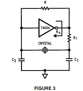
To generate a 1 MHz square wave, it is advisable to use a higher frequency crystal and divide it down for two reasons: (1) 4 MHz crystals are generally more affordable and easier to procure than 1 MHz crystals;...
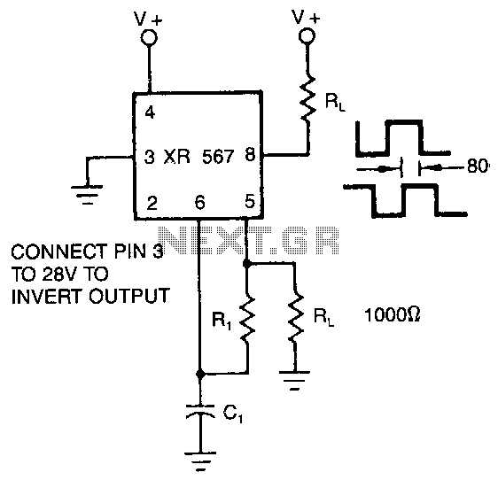
The XR-567 operates as a precision oscillator, providing two distinct square-wave outputs at pins 5 and 8, which are nearly in quadrature phase with one another. Due to the internal biasing configuration, the typical phase shift between the two...
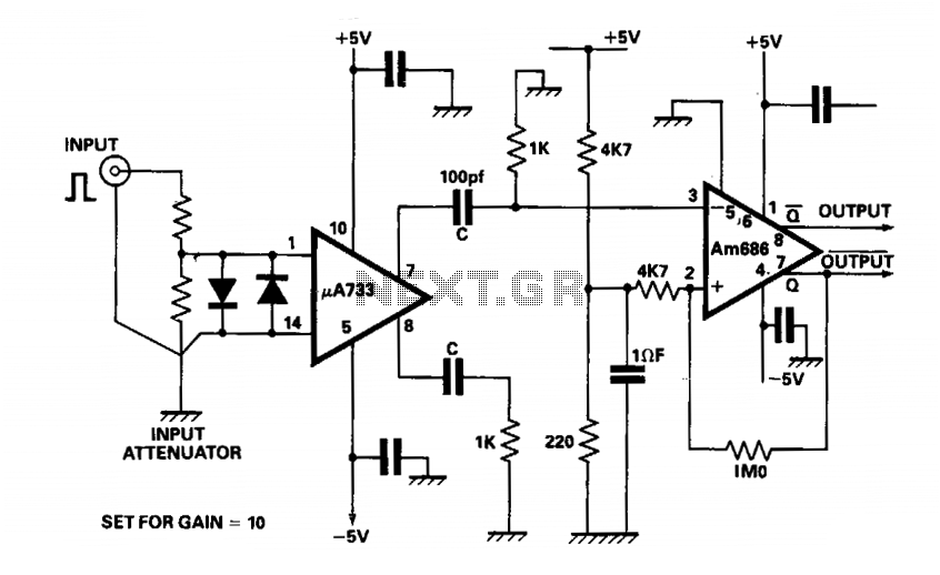
The output of a video amplifier is differentiated before being fed to a Schottky comparator. The propagation delay is typically reduced to 10 ns. The output pulse width is determined by the value of C, 10 pF, resulting in...
A low phase noise voltage-controlled oscillator circuit is presented, specifically integrated within the MAX2605-2609 voltage-controlled oscillator series. The circuit features a tuning voltage control terminal, allowing for adjustable oscillation frequency through a DC voltage input. The output of the...
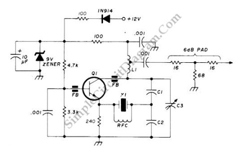
This circuit operates at a frequency range of 90-125 MHz and is particularly useful for VHF/UHF converters. It provides an output power of 5 to 15 mW. The circuit can utilize high-quality fifth- or seventh-over-tone crystal types. A ferrite...
This gated 1-kHz oscillator provides a press-to-turn-on functionality, with waveforms available at the output of pin 3 and across capacitor CI. The gated 1-kHz oscillator circuit is designed to produce a square wave output that can be activated by a...