
Gated 1Khz Oscillator (Normally Off) Circuit
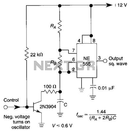
The gated 1-kHz oscillator circuit is designed to produce a square wave output that can be activated by a momentary press of a switch. The oscillator operates at a frequency of 1 kHz, which is suitable for various timing and control applications. The circuit typically includes a timing resistor and capacitor that determine the frequency of oscillation, while the gating mechanism allows for the output to be enabled or disabled based on an external control signal.
Pin 3 serves as the primary output of the oscillator, delivering the square wave signal. This output can be utilized to drive other components or circuits, such as LEDs, relays, or microcontrollers. The capacitor CI, which is connected across the output, plays a critical role in shaping the waveform and filtering any noise present in the signal. The capacitor may also aid in stabilizing the output by providing a low-pass filtering effect, ensuring that the output waveform is clean and well-defined.
The press-to-turn-on feature enhances user interaction, allowing for easy activation of the oscillator without the need for a continuous switch press. This can be particularly useful in applications where a temporary signal is required, such as in timers or pulse generators. The design can be tailored to include additional features, such as adjustable frequency or amplitude, by modifying the component values or adding further circuitry.
Overall, this gated 1-kHz oscillator is a versatile component that can be integrated into various electronic designs, providing reliable timing signals with straightforward activation. This gated 1-kHz oscillator offers press-to-turn-on operation, A, and waveforms at the output of pin 3 and across CI, B. 🔗 External reference
Related Circuits
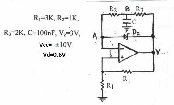
This circuit appears to be a Schmitt trigger oscillator. Based on the configuration of the resistors and capacitor, it is likely functioning as a sawtooth wave generator, with resistors R2 and R3 influencing the slope of the rising and...
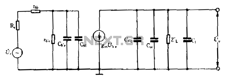
Common emitter amplifier circuit with resistance and capacitance coupling. The common emitter amplifier circuit is a fundamental configuration in analog electronics, widely utilized for its ability to amplify voltage signals. This circuit employs a bipolar junction transistor (BJT) as the...
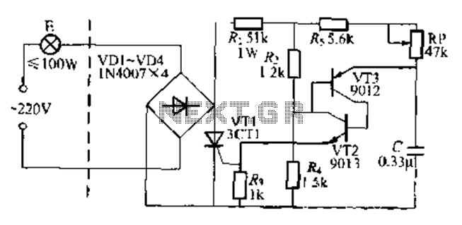
The circuit is a one-way ordinary transistor-triggered dimmer light circuit. It uses a complementary amplifier configuration with transistors VT2 and VT3 to form the thyristor trigger circuit for VT1. The circuit operates with a 220V alternating current through the...
This is an FSK modulation circuit composed of the 74LS74. The FSK modulation circuit does not include a phase-locked loop (PLL) or a high-Q bandpass filter, eliminating the need for tuning adjustments in the high-frequency modulation circuit. The two...
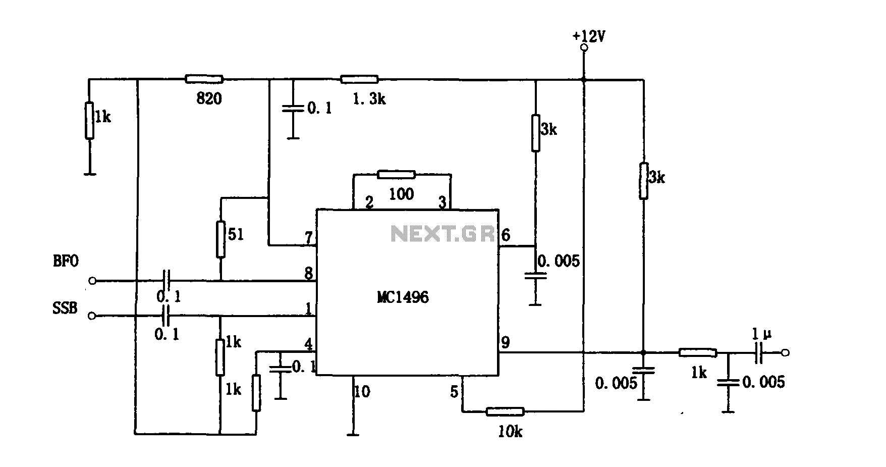
The provided information pertains to a detector circuit designed for multiplication. This circuit functions as a single-sideband amplitude modulation (SSB AM) signal detector, utilizing its principles to demodulate the received single-sideband signal and recover the transmitted signal. It employs...
Many households still have tube-type television sets. Connecting one of these large televisions to a stereo system to enhance sound quality is generally straightforward, as numerous SCART to Cinch adapters are available in accessory stores. However, some television sets...
Warning: include(partials/cookie-banner.php): Failed to open stream: Permission denied in /var/www/html/nextgr/view-circuit.php on line 713
Warning: include(): Failed opening 'partials/cookie-banner.php' for inclusion (include_path='.:/usr/share/php') in /var/www/html/nextgr/view-circuit.php on line 713