
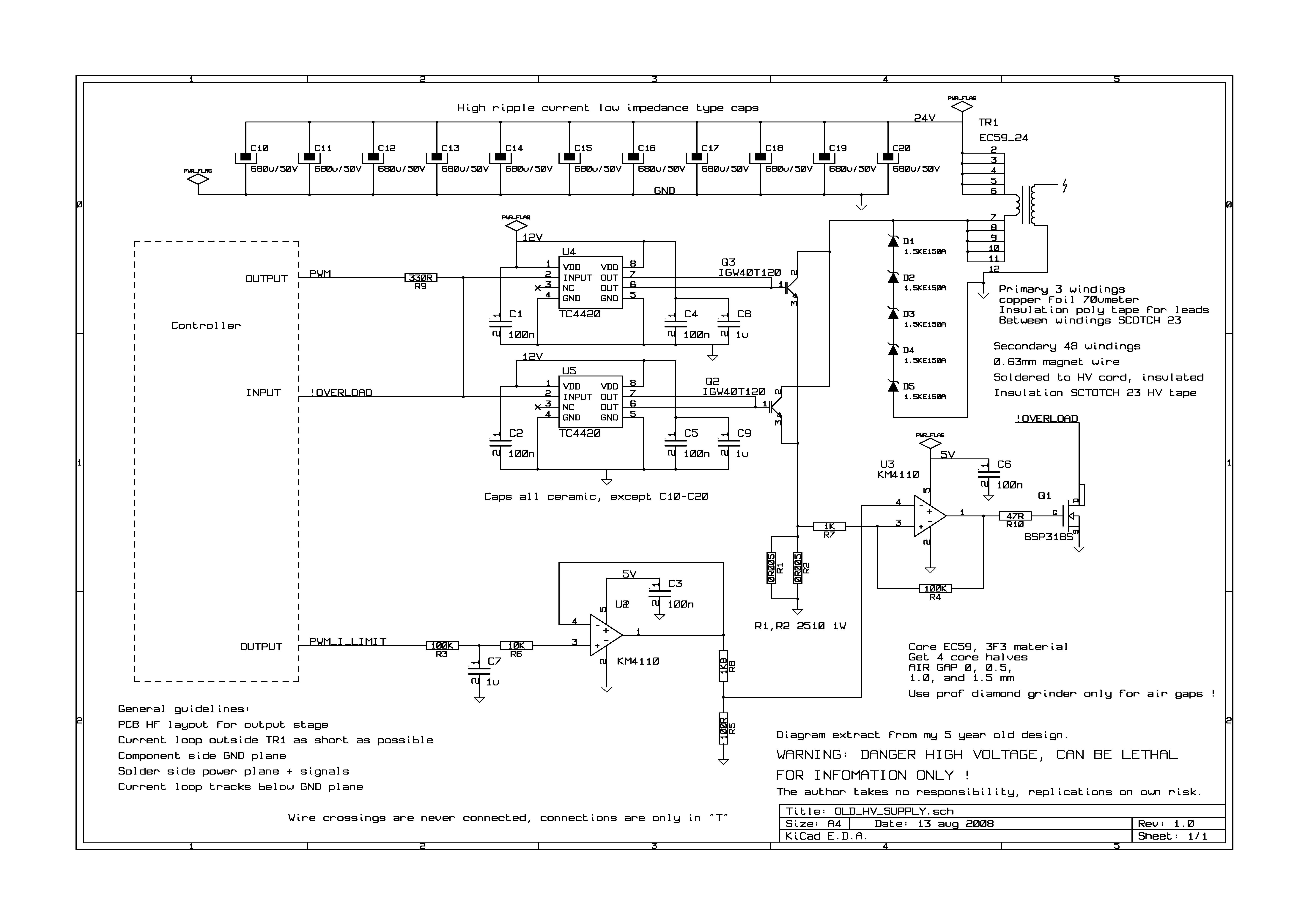
Monostable oscillator

The described circuit configuration utilizes a video amplifier followed by a Schottky comparator to process video signals effectively. The video amplifier enhances the amplitude of the input video signal, ensuring that it is suitable for further processing. The differentiation stage introduces a high-pass filter effect, allowing rapid changes in the signal to be detected while attenuating lower frequency components. This differentiation is crucial for applications requiring precise timing and fast response.
The Schottky comparator, known for its low propagation delay, is employed to compare the differentiated output signal against a predetermined reference level. The typical propagation delay of 10 ns ensures that the circuit can operate at high speeds, making it suitable for applications in video processing where timing is critical.
The output pulse width, influenced by the capacitor value (C = 10 pF), is approximately 90 ns. This pulse width can be adjusted by changing the capacitance value, allowing for flexibility in applications requiring different timing characteristics. The overall design emphasizes minimal delay and precise pulse generation, making it ideal for high-speed video signal processing in various electronic systems.The output of a video amplifier is differentiated before being fed to a Schottky comparator. The propagation delay is reduced to typically 10ns. The output pulse width is set by the value of C, lOOpf giving a pulse of about 90ns duration. It using video amplifier and comparator.
Related Circuits
This circuit operates at 36V with a current of 500mA on the front side, while it features a 36V charging capability on the back side. The brightness is comparable to that of a 240V light bulb, considering it is...
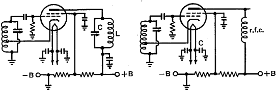
One of the significant challenges in designing vacuum-tube oscillators is maintaining a constant frequency despite mechanical vibrations, temperature fluctuations, voltage variations in the supply lines, and changes in the load power drawn from the circuit. The effects of variable...
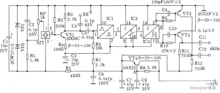
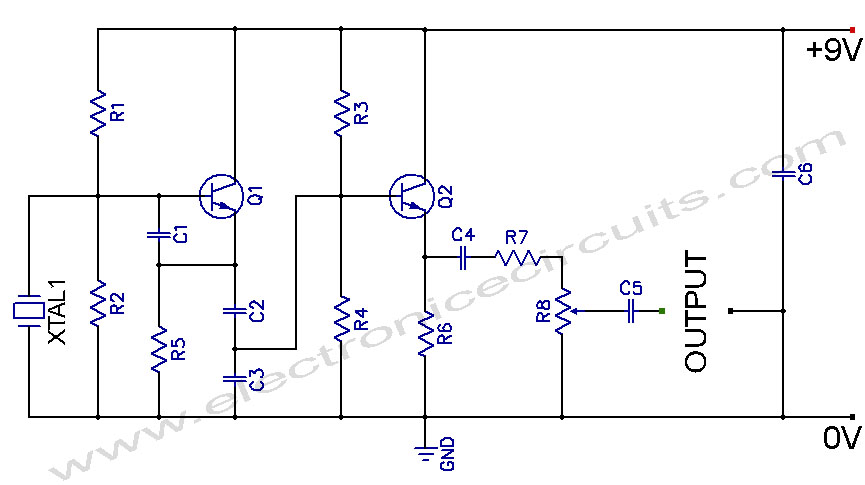
This circuit is a 1024 kHz temperature-compensated crystal oscillator. The circuit theory is illustrated. Due to the low output signal level of the circuit, a buffer using the following transistor VT1 is implemented for amplification. The base bias resistor...
This is the first oscillator that was built. Various resources such as books, magazines, and online schematics were reviewed. Most of the designs encountered were either Colpitts or Hartley oscillators. While these designs are relatively straightforward, they require specific...
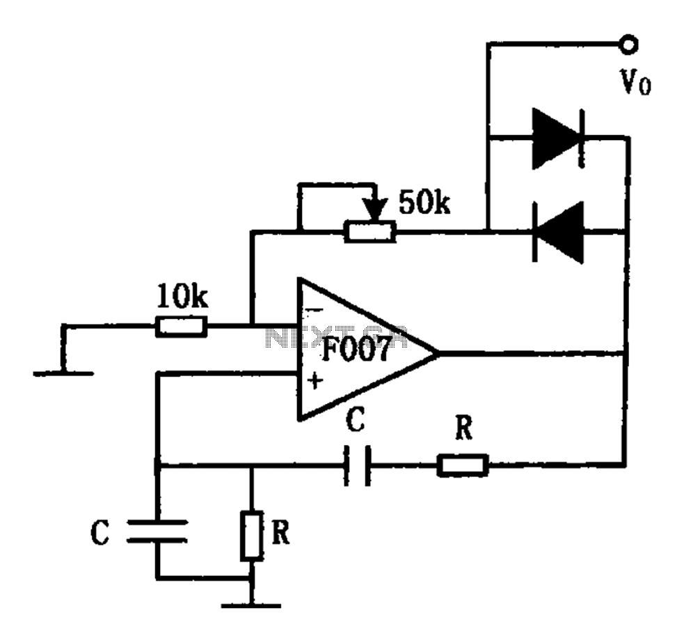
The stable sine wave oscillator circuit is designed to maintain consistent oscillation. The loop gain must be carefully managed; if the gain is excessive, waveform distortion occurs, while insufficient gain can lead to cessation of oscillation. This circuit employs...
Crystal Controlled Oscillator Circuit. This general-purpose signal source is highly effective in signal-tracing applications. The output level is adjustable. The crystal-controlled oscillator circuit is designed to provide a stable and precise frequency output, which is essential for various electronic applications,...