
How to connect a crystal oscillator to generate Square wave

To implement a circuit that generates a 1 MHz square wave using a higher frequency crystal, a typical approach involves the use of a 4 MHz crystal oscillator circuit. This circuit can be configured using a simple inverter or a series of inverters to shape the output signal. The crystal oscillator circuit would typically consist of a crystal connected in the feedback loop of an inverter gate, which will oscillate at the frequency of the crystal.
Once the 4 MHz signal is generated, it can be divided down to 1 MHz using a frequency divider circuit. A common method for frequency division is to use a flip-flop, specifically a D-type or T-type flip-flop. By connecting the output of the inverter to the clock input of the flip-flop, the output frequency will be halved. The resulting square wave will have a 50% duty cycle, which is ideal for many digital applications.
In summary, the circuit design involves the following key components: a 4 MHz crystal oscillator, one or two inverters for signal shaping, and a flip-flop for frequency division. This arrangement ensures that a clean, stable 1 MHz square wave is produced with the desired duty cycle, suitable for various electronic applications.If you want a 1MHz square wave, I would suggest using a higher frequency crystal and dividing it down, for two reasons: (1) 4MHz crystals are apt to be cheaper and easier to find than 1MHz ones; (2) Getting a 50. 0000% duty cycle from a crystal is a bit tricky; by contrast, if one converts the signal from a crystal into a pulse wave (just pass it through an inverter or two) and
divides that down, the resulting wave will "naturally" have a perfect 50% duty cycle. supercat Nov 19 `12 at 16:52 🔗 External reference
Related Circuits
Hartley oscillators are inductively coupled, variable frequency oscillators that can be series or shunt fed. They feature a center-tapped inductor and a tuning capacitor, which simplifies the circuit construction. The schematic includes a buffer stage and an amplifier stage...
This simple circuit utilizes a 741 operational amplifier (op-amp) in differential mode as a continuity tester. The voltage difference between the non-inverting and inverting inputs is amplified by the op-amp's full open-loop gain. Initially, the 470kΩ and 10kΩ resistors...
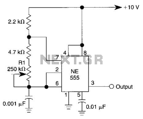
This simple square-wave generator produces a variable frequency output ranging from 2800 Hz to 80 kHz, as indicated by the specified values. The frequency can be adjusted using potentiometer R1. The square-wave generator circuit typically employs a combination of resistors,...
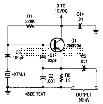
This is a simple Colpitts crystal oscillator for 1 to 20 MHz, which can be easily constructed from spare parts, provided that a crystal is available. The Colpitts oscillator is a type of electronic oscillator that utilizes a combination of...
After disappointing results with a transformer-based component tester, there is an interest in generating a ±10 V sine wave at approximately 50 Hz using minimal components. While an ATmega microcontroller could achieve this, it may be considered excessive, requiring...
This simple circuit is sure to have the police beating a path to your door - however, it has the added advantage of alerting you to their presence even before their footsteps fall on the doormat. The circuit transmits...