
10W 10M Linear Amplifier Circuit
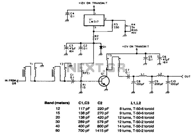
This linear amplifier circuit is designed to operate efficiently within the 10-meter amateur radio band, delivering a peak envelope power (PEP) output of 10 watts. The initial drive requirement is relatively low at 1.25 watts, making it suitable for low-power applications. The use of bifilar windings in the transformers T1, T2, and T3, wound on an FT-50-43 toroidal core, enhances the amplifier's ability to function across a broad frequency range, minimizing losses and improving overall performance.
The circuit layout should incorporate additional filters for other amateur radio bands if the operator desires multi-band functionality. These filters can be designed using standard LC filter topologies, ensuring that unwanted harmonics and spurious emissions are effectively attenuated while allowing the desired signals to pass through.
For capacitors C1 and C2, the recommendation to use #26 wire is crucial for maintaining the integrity of the circuit and ensuring minimal parasitic inductance. The choice of capacitors should be made carefully, selecting components that are as close as possible to the specified values to maintain the desired bandwidth and performance characteristics.
It is important to note that as the operating frequency of the amplifier decreases, there is a corresponding increase in gain. This phenomenon can lead to potential instability within the amplifier circuit. To counteract this effect, the implementation of RC feedback is advisable. This feedback mechanism can help stabilize the amplifier by reducing gain at lower frequencies, thereby ensuring consistent performance without oscillation or distortion.
The values utilized in this design have been referenced from the QRP Notebook by Doug DeMaw, which serves as a valuable resource for amateur radio enthusiasts and engineers alike, providing tested and proven designs for low-power RF applications. This linear amplifier delivers 10-W PEP output; with 1.25-W drive on 10 m. Tl, T2, and T3 are 10 turns of bifilar windings on an FT-50-43 toroidal core. The transformers are broadband. Filters for other bands, if desired, are shown. Note: use #26 wire for C1 and C2. Use capacitors that are closest to these suggested values. As the operating frequency decreases, the gain will Increase as well as the possibility for instability. You may have to use RC feedback to negate this effect. Values for the above table were obtained from the QRP Notebook by Doug DeMaw. 🔗 External reference
Related Circuits

This alarm system utilizes a loud police siren to deter potential intruders. Activated by a single clap, the circuit triggers the alarm for three minutes, which is adequate to alert nearby residents. The design incorporates a sensitive clap switch...
Frequency-Shift Keying (FSK) is a type of frequency modulation where the modulating signal alters the output frequency between specific predetermined values. When issues occur during the demodulation of FSK signals, utilizing an FSK filter circuit can be beneficial. Frequency-Shift Keying...
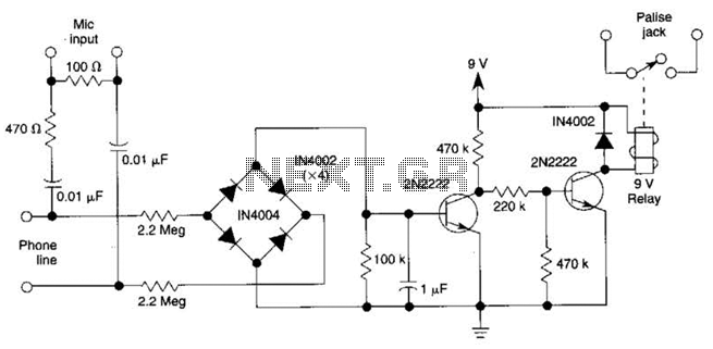
The DC voltage on a telephone line typically ranges from 45 to 50 V when on-hook and drops to around 6 V when off-hook. This circuit utilizes the voltage drop to activate a relay, which in turn controls a...
Utilize a V2-400 subwoofer amplifier for the center channel, and incorporate a separate Digital Converter specifically for the added subwoofer amplifier to initiate a V5.1 system. Place all preamplifiers within the subwoofer enclosure and design a digital control box...
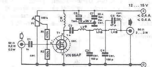
By using this RF amplifier, small power transmitters of 200 mW can be upgraded to reasonable power transmitters, ranging between 2 and 3 W. The circuit is straightforward. The output filter network suppresses noise by at least 55 dB....
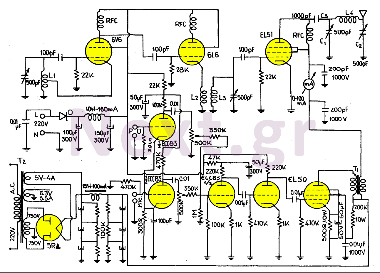
This transmitter, equipped with a quality antenna and utilized under optimal conditions, can achieve a range exceeding 45 km. The configuration benefits from the output lamp's elevation, enhancing the fidelity of the transmitted signal. The 6V6 lamp is employed...
Warning: include(partials/cookie-banner.php): Failed to open stream: Permission denied in /var/www/html/nextgr/view-circuit.php on line 713
Warning: include(): Failed opening 'partials/cookie-banner.php' for inclusion (include_path='.:/usr/share/php') in /var/www/html/nextgr/view-circuit.php on line 713