
10W Audio Amplifier with Bass-boost
The audio amplifier design leverages the NE5532 dual operational amplifier, which is renowned for its high performance in audio applications. The circuit is configured to operate within a supply voltage range of ±18V, ensuring that the output power remains within the specified limits of 9.5 to 11.5 Watts. This power output is suitable for driving small loudspeaker cabinets, which are commonly used in various audio applications.
To enhance the low-frequency response, a bass-boost control is integrated into the feedback loop. This feature allows users to compensate for the natural roll-off of bass frequencies that occurs in smaller speaker systems. The bass boost can provide a significant enhancement of up to +16.4 dB at 50 Hz, making it possible to achieve a fuller sound profile without introducing distortion or compromising audio quality.
The frequency response characteristics of the amplifier are designed to ensure clarity across the audio spectrum. When the bass control is set to its lowest position, the amplifier still maintains a gentle rising frequency response. This includes an increase of +0.8 dB at 400 Hz, +4.7 dB at 100 Hz, and +6 dB at 50 Hz, all referenced to 1 kHz. This response curve indicates that even without bass enhancement, the amplifier is capable of delivering a balanced audio output.
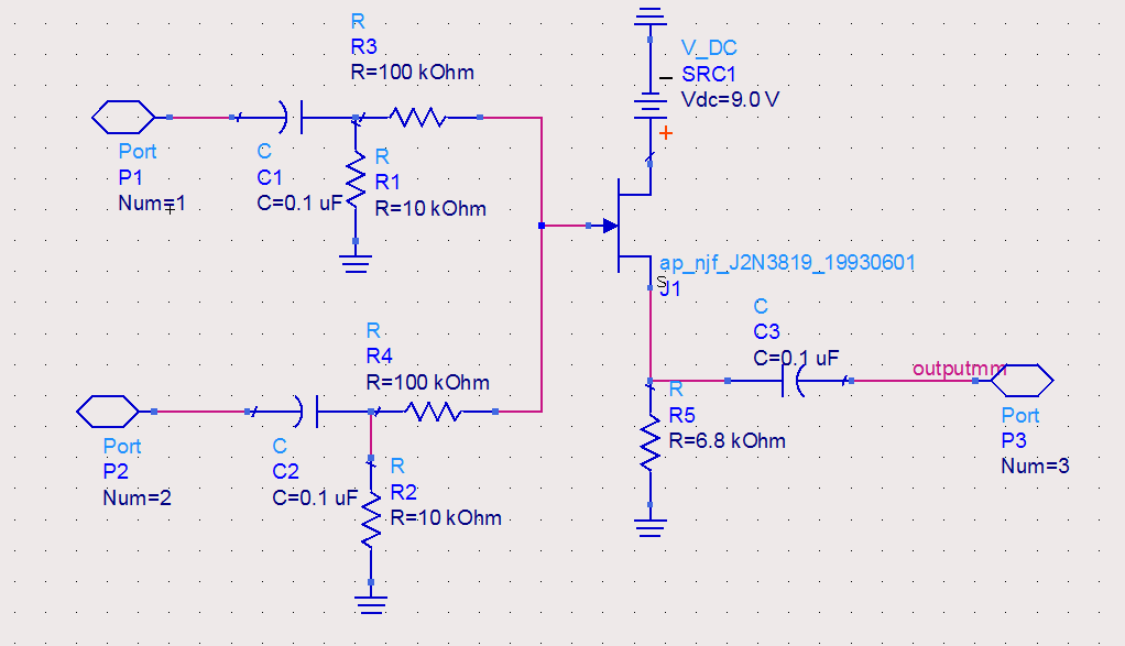
Grounding is a critical aspect of the circuit design, as improper grounding can lead to unwanted hum and ground loops. To mitigate these issues, it is recommended that all ground connections for components such as J1, P1, C2, C3, and C4 be tied to a single grounding point. Additionally, C9 should be connected to the output ground to maintain signal integrity and minimize noise interference.
Overall, this audio amplifier design provides a practical solution for users seeking an effective and high-quality amplifier that can be easily assembled using readily available components. The incorporation of bass-boost functionality and careful attention to grounding enhances the performance and usability of the amplifier in various audio applications.This design is based on the 18 Watt Audio Amplifier, and was developed mainly to satisfy the requests of correspondents unable to locate the TLE2141C chip. It uses the widespread NE5532 Dual IC but, obviously, its power output will be comprised in the 9. 5 - 11. 5W range, as the supply rails cannot exceed G‚ ±18V. As amplifiers of this kind are freq uently used to drive small loudspeaker cabinets, the bass frequency range is rather sacrificed. Therefore a bass-boost control was inserted in the feedback loop of the amplifier, in order to overcome this problem without quality losses. The bass lift curve can reach a maximum of +16. 4dB @ 50Hz. In any case, even when the bass control is rotated fully counterclockwise, the amplifier frequency response shows a gentle raising curve: +0.
8dB @ 400Hz, +4. 7dB @ 100Hz and +6dB @ 50Hz (referred to 1KHz). A correct grounding is very important to eliminate hum and ground loops. Connect in the same point the ground sides of J1, P1, C2, C3 &C4. Connect C9 at the output ground. 🔗 External reference
Related Circuits
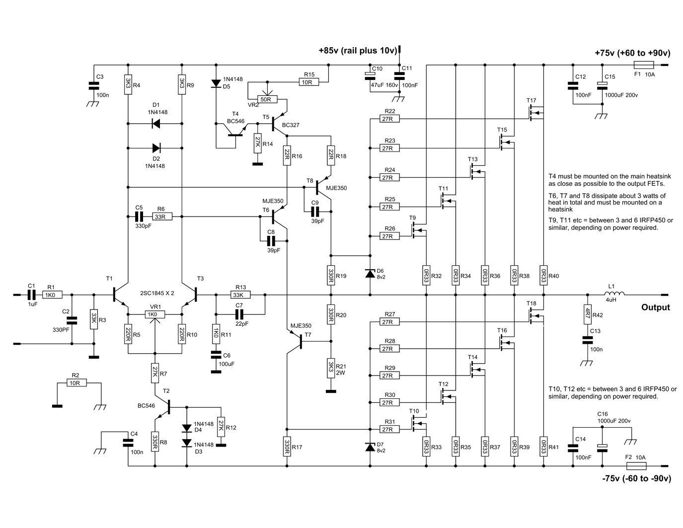
This circuit is a Power Amplifier designed to deliver an output power exceeding 600 Watts for speakers with an impedance of 4 Ohms. The high-power amplifier circuit utilizes six n-channel MOSFETs in the output stage, which alone provides approximately...
The modular Portable Mixer design featured on these web pages has gained popularity among many amateurs; however, some users have requested a simpler device primarily for mixing mono signals. This design aims to meet those requirements, incorporating three inputs...
The circuit utilized was primarily designed for audio mixing, featuring inputs from both a triangular wave generator and a noise generator. These signals are processed through an audio mixer to create the final output wave. This audio mixing circuit integrates...
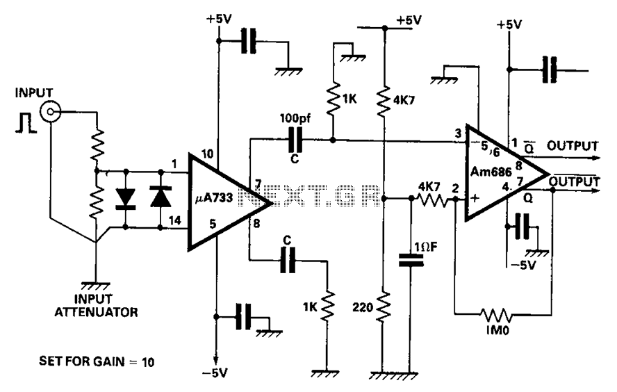
A video amplifier output arrives at a differentiation stage before the Schottky comparator. The typical propagation delay is reduced to 10 ns. The output pulse width is determined by the capacitance value, where C is 100 pF, resulting in...
The amplifier drives a pair of speakers using two LM3876 amplifier chip circuits (50 watts per channel) or a pair of headphones with Meier Crossfeed through a clarifier and a dual OPA2134 Opamp. It features four selectable band inputs...
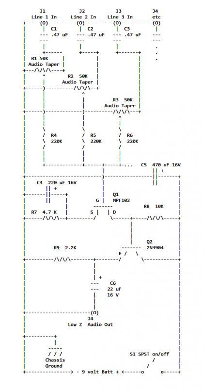
If two of these circuits are made in the same enclosure for stereo, then there can be a single power supply to run both of them. There should be a resistor in series with the incoming 9V+ lead so...
Warning: include(partials/cookie-banner.php): Failed to open stream: Permission denied in /var/www/html/nextgr/view-circuit.php on line 713
Warning: include(): Failed opening 'partials/cookie-banner.php' for inclusion (include_path='.:/usr/share/php') in /var/www/html/nextgr/view-circuit.php on line 713