
Audio Mixer transistorized circuit
The described circuit serves as a basic audio mixer designed for stereo applications, where two identical circuits are housed within a single enclosure. This configuration allows for a unified power supply, enhancing efficiency and minimizing the overall footprint of the device.
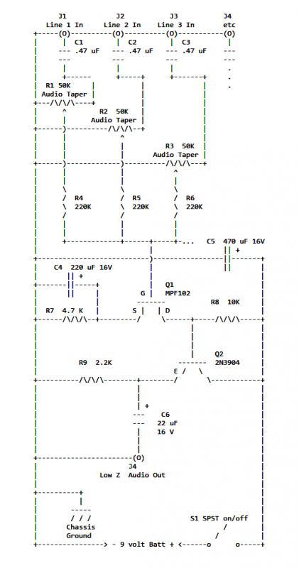
To mitigate potential issues such as crosstalk and unwanted noise during power-up, a resistor (R7) is employed in series with the 9V power supply lead. The precise value of R7 is critical and should be adjusted based on the specific characteristics of the field-effect transistors (FETs) used in the circuit. The goal is to achieve a voltage of half the supply voltage at the junction between the emitter of transistor Q2 and resistor R9, which ensures optimal operating conditions for the FETs.
The output stage includes an earphone jack, facilitating direct audio output. Each channel of the stereo mixer employs a transformer with a primary impedance of 1K ohms and a secondary impedance of 8 ohms. The primary side connects to the output jack, while the secondary side interfaces with the earphone, allowing for effective impedance matching and audio signal transfer.
Further enhancements can be integrated into this basic mixer design. The addition of one or more microphone preamps can significantly improve the versatility of the mixer by allowing it to accommodate low-impedance microphones. These preamps may also include transformers to ensure proper impedance matching. Additionally, visual feedback mechanisms such as VU level meters or LED bar graphs can be incorporated, providing users with a clear indication of audio levels and facilitating better mixing and monitoring capabilities.
Overall, this circuit design provides a solid foundation for a stereo audio mixer, with opportunities for customization and expansion to suit various audio applications.If two of these circuits are made in the same enclosure for stereo, then there can be a single power supply to run both of them. There should be a resistor in series with the incoming 9V+ lead so as to minimize crosstalk, and reduce the PLOP when it's powered on.
R7 value will depend on the FET characteristics, which varies from FET to FET. Adjust the value to get half the supply voltage at the junction of the emitter of Q2 and R9.
An earphone jack can be put on the output. A 1K to 8 ohm transformer can be used for each channel, two for stereo. The 1K primary would go to the output jack. The 8 ohm secondary would go to the earphone. Other features can be added to this basic mixer. One or more microphone preamps could be added. A VU level meter or LED bargraph can be added. The microphone preamps could have a transformer to match a low impedance microphone to the preamp input.🔗 External reference
Related Circuits
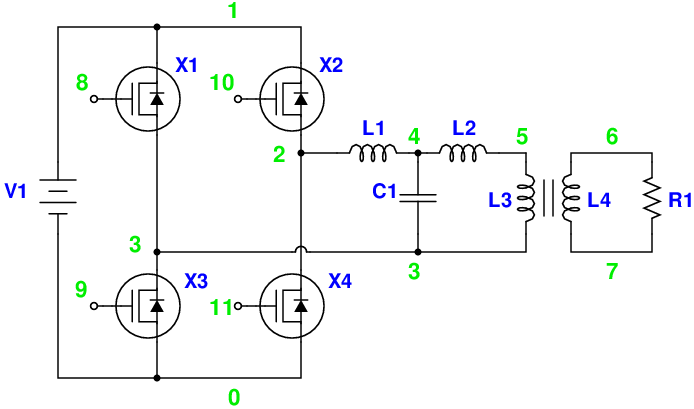
Magic Sinewave Analysis using SPICE and a Simple Inverter Circuit. This document discusses the analysis of a sinewave signal generated by a simple inverter circuit using SPICE simulation software. The inverter circuit is designed to convert a DC input voltage...
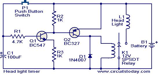
This circuit is a compact timer that keeps the headlights of a car on for approximately 1.5 minutes before turning them off. Incorporating this circuit into a vehicle allows access to dark areas without the need to return and...
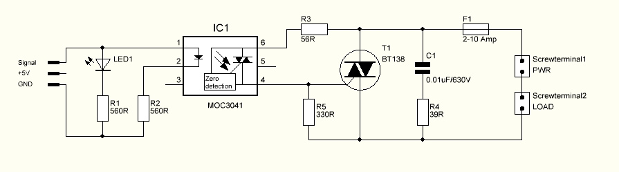
The triac is expected to activate and illuminate the light at nearly 100% brightness; however, it does not turn on at all. If the gate is continuously triggered (i.e., a constant voltage is applied to the gate), the light...
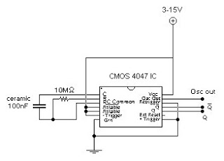
This circuit generates a digital square wave that can be displayed directly or utilized to drive additional circuits. It employs the CMOS 4047 Low-Power Monostable/Astable Multivibrator, as referenced in Tom Duncan's "Adventures with Digital Electronics" book, to control a...
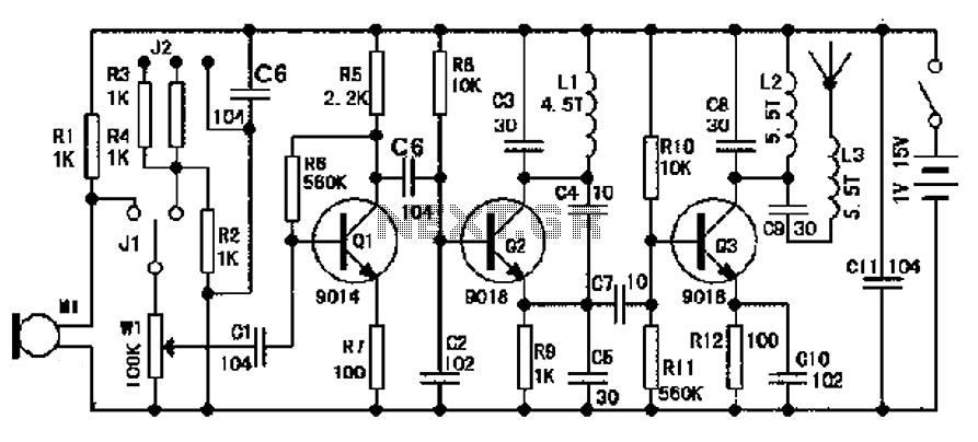
The design of an FM radio transmission frequency band enables compatibility with any FM radio receiver, allowing the high-frequency signal to be transmitted and restored from an audio signal. This technology serves various applications. Applications of a wireless microphone...
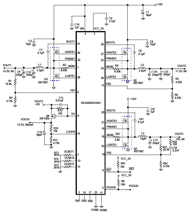
The ISL9440 quad-output synchronous buck controller IC can be utilized to design a highly efficient electronic circuit power supply that delivers four distinct fixed output voltages. The ISL9440 integrates three PWM controllers and one low dropout linear regulator controller,...