
600 Watt Mosfet Power Amplifier with PCB Schematic Diagram
The Power Amplifier circuit is engineered to handle significant power output while maintaining efficiency and performance. The use of n-channel MOSFETs, specifically the IRFP460 model, is critical due to their high current and voltage ratings, which are essential for achieving the desired output levels. The circuit design incorporates a robust power supply that is capable of delivering the necessary voltage and current to support the operation of the MOSFETs under high load conditions.
In the output stage, the configuration of the 12 MOSFETs is designed to work in parallel, which allows for the distribution of the load across multiple devices, thus minimizing the thermal stress on each individual component. This parallel configuration also enhances the overall output power capability of the amplifier. Proper heat dissipation mechanisms, such as heat sinks or fans, should be integrated into the design to ensure that the MOSFETs operate within safe temperature limits, thereby prolonging their lifespan and maintaining circuit reliability.
The PCB layout is meticulously designed to accommodate the high current paths required by the power amplifier. It includes wide traces for power distribution and strategically placed components to minimize noise and interference. The layout also considers the placement of decoupling capacitors near the MOSFETs to provide stable power and reduce voltage spikes during operation.
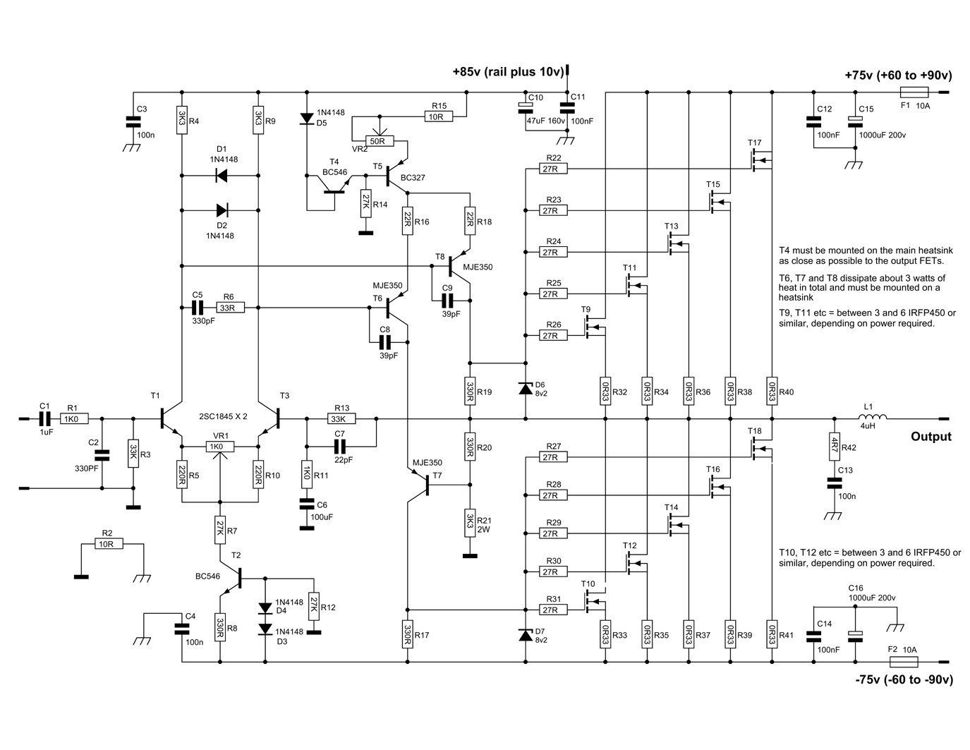
Overall, this Power Amplifier circuit is suitable for high-performance audio applications, providing a powerful audio output while ensuring stability and efficiency through careful component selection and circuit design. The accompanying PCB layout and power supply design further facilitate the implementation of this circuit in practical applications.Here is a circuit Power Amplifier with output power of more than 600 Watt speakers with impedance of 4 Ohm. Power Amplifier circuit with high power uses n-channel MOSFETs 6 in the output stage alone is giving about 400Watt power.
And to make more than 600Watt need to use 12 N-Channel MOSFETs. One of the construction sequence to produce more output power of 900W using 12 IRFP460 MOSFET. Here is a Power Amplifier Circuit Diagram, and the Power Supply is suited for this amplifier. I also include a PCB Layout Design for the power amplifier and its power supply, you can see below. You are reading the Circuits of 600 Watt Mosfet Power Amplifier with PCB And this circuit permalink url it is 🔗 External reference
Related Circuits
Self-switching power supply. One of the main features of the regulated power supply circuit being presented is that, although a fixed-voltage regulator LM7805 is used in the circuit, its. The self-switching power supply circuit utilizes the LM7805 voltage regulator to...
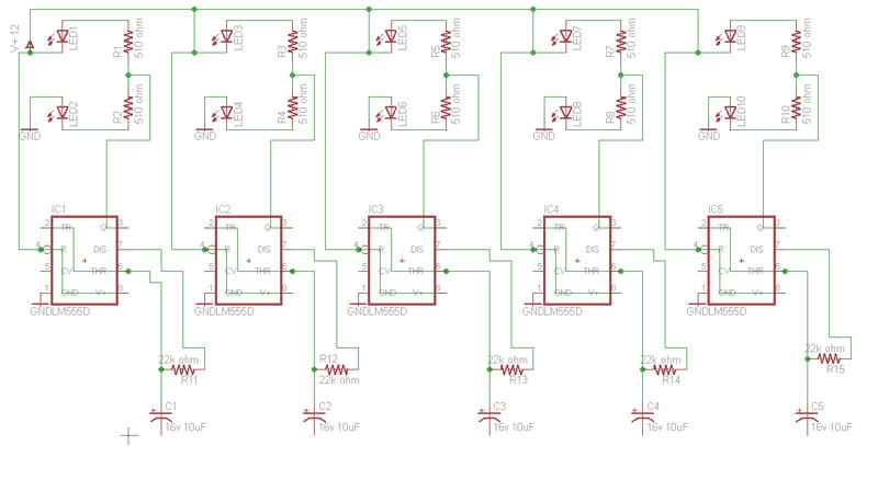
Build a circuit that will flash five pairs of LEDs at variable rates. To achieve this, a circuit utilizing five NE555 timers has been designed. Trim pots will be used to control the variable flash rate. Assistance is needed...
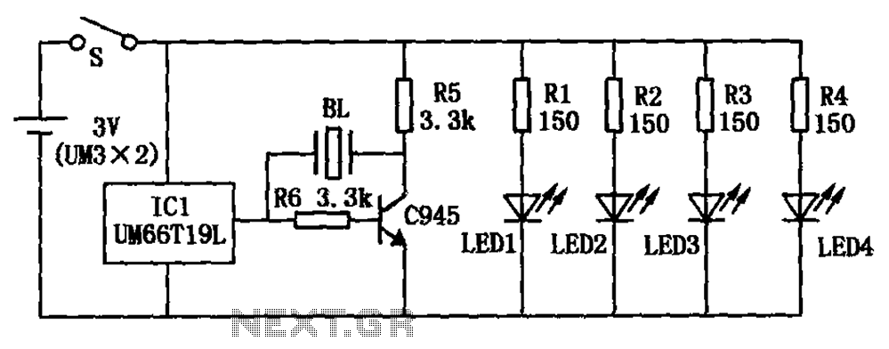
The circuit diagram of a flash music gyro consists of three music integrated circuits (IC1: UM66T19L) and multiple light-emitting diodes (LED1 to LED4). During rotation, the centrifugal force activates the centrifugal switch (S1), which powers the four light-emitting diodes,...
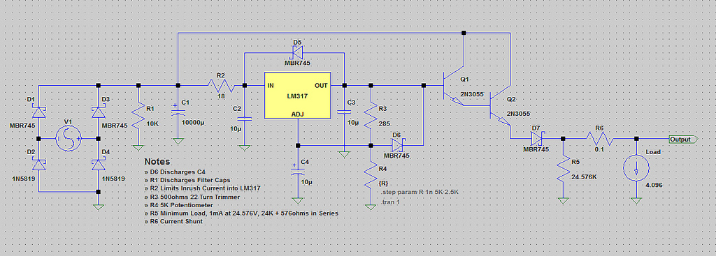
The voltage range will be from 0V to 24V, and the current is not expected to exceed 4A. A microcontroller and an LCD could potentially be added to measure voltage and current. The schematic appears to be generally acceptable....
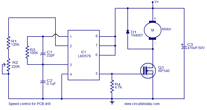
This circuit is designed for controlling the speed of DC-operated PCB drills. The core component of this circuit is the ICLM3578, an efficient integrated switching regulator suitable for such applications. The LM3578 features separate inverting and non-inverting feedback inputs...
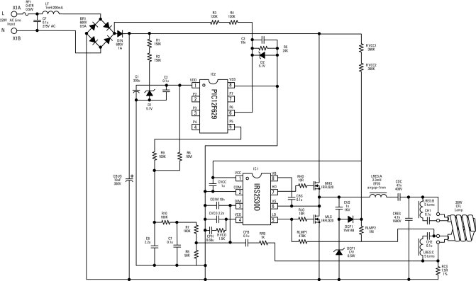
Electronic ballasts for dimming fluorescent lamps require a control interface for the user to set the desired lamp brightness level. Existing interface circuits include a 1-to-10 Vdc interface, a digitally-addressable lighting interface (DALI), triac-based wall dimmers, three-way lamp sockets,...