
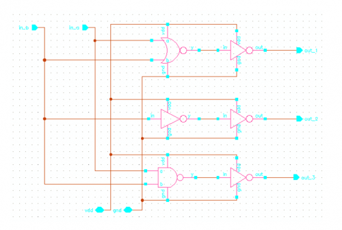
12 bit Digital to Analog Converter
Digital to analog converters (DACs) serve a critical role in modern electronic systems by converting digital signals, which are represented in binary form, into analog signals that can be used in various applications. These converters are essential for interfacing digital devices with the analog world, enabling the playback of audio, the display of video, and the transmission of signals in telecommunications.
A typical DAC circuit comprises several key components: a digital input interface, a resistor ladder or a switched-capacitor network, an operational amplifier for signal conditioning, and an output stage. The digital input interface accepts binary data, which can be in various formats such as binary-coded decimal (BCD) or two's complement. The resolution of the DAC, often expressed in bits, determines the granularity of the output signal, with higher resolutions providing finer control over the analog output.
The conversion process commonly employs techniques such as binary-weighted or R-2R ladder architectures. In a binary-weighted DAC, each bit of the digital input corresponds to a specific weight in the resistor network, while an R-2R ladder DAC utilizes a repeating resistor network to achieve the same effect with fewer component values, enhancing precision and reducing complexity.
The output of the DAC is typically a stepped voltage signal, which may require further conditioning via an operational amplifier to smooth out the steps and provide a continuous analog signal. This output can then be utilized in various applications, including audio amplifiers, video signal processing, and control systems.
In summary, digital to analog converters are fundamental components in bridging the digital and analog domains, facilitating a wide range of applications from consumer electronics to industrial automation. Their design and implementation are critical to achieving high performance and fidelity in signal conversion.h5. INTRODUCTION Digital to analog converters are one of the most commonly employed circuits in many applications involving digital video, signal processing, test e.. 🔗 External reference
Related Circuits
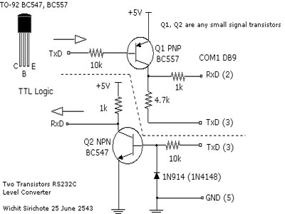
When connecting a microcontroller project to a COM port on a PC, an RS-232 converter is required. Various chips can accomplish this task, such as the MAX232 and DS275. However, for a simple and cost-effective RS-232 converter, the following...
There are many individuals interested in listening to frequencies within the VHF range of 108 to 132 MHz. This VHF AM converter is designed to convert signals from a frequency band of 106 to 150 MHz, allowing users to...
This project utilizes the ISD2560P integrated circuit (IC), which enables the recording of 60 seconds of audio and subsequent playback with high fidelity. The schematic indicates that the input source is an electret microphone. If a dynamic microphone is...
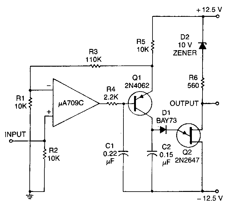
This circuit consists of a UJT oscillator in which the timing charge capacitor C2 is linearly dependent on the input signal voltage. The charging current is set by the voltage across resistor R5, which is accurately controlled by the...
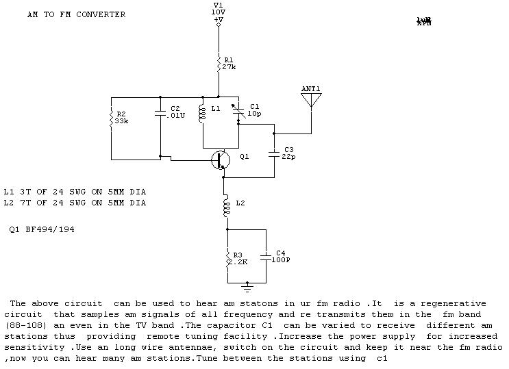
The circuit described is designed to enable the reception of AM stations on an FM radio. It operates as a regenerative circuit, sampling AM signals across various frequencies and retransmitting them within the FM band (88-108 MHz) and even...
This project is considered intermediate to advanced and is not recommended as a first project for individuals who are new to synthesizers or electronics. The circuit and some explanations are provided, assuming that the builder has significant experience in...