
Digital Voice Record and Playback Project by ISD2560P
The ISD2560P IC is a versatile device designed for voice recording applications, featuring built-in analog circuitry for audio processing. The recording quality is determined by the microphone's characteristics and the circuit's design, making the choice of an electret microphone beneficial for capturing clear audio signals.
The use of the 7805 voltage regulator ensures that the ISD2560P operates at its required voltage level, providing stable performance across varying supply conditions. The amplifier circuit built around the LM386 is essential for enhancing the audio output, as the ISD2560D's internal amplifier may not provide sufficient drive for larger speakers. By integrating a potentiometer, users can easily adjust the output level to suit different listening environments.
The schematic layout should clearly depict the connections between the ISD2560P, microphone, control buttons, power supply, and the amplifier circuit. Attention should be given to the grounding and power distribution to minimize noise and ensure reliable operation. This project serves as an excellent platform for learning about audio recording systems and the integration of various electronic components for sound applications.This project is based on ISD2560P IC which allows you to record 60 seconds voice and then playback it with very high quality. As shown in the schematic, the input soruce is an electret microphone. If a dynamic microphone is used, R2, R3, R4 resistors and C3, C5, C7 capacitors will be omitted and microphone will be connected to the 17 and 18 numbered p
ins directly. Since it has better frequency response, we choose electret microphone in this project. Controlling the circuit is very simple. Sw1 switches between record and playback modes. Push button B1 is used for start and pause functions. B2 stops the process. To record voice, first move Sw1 to the record position and then push B1 once. IC will start recording and during this process red LED will bright. One push to B1 pauses and second push continues recording. You can record 60 seconds by this way. To stop recording push B2. To listen the voice recorded before, move Sw1 to playback position then push B1. During the playback process red LED will bright again. One push to B1 pauses and second push continues playing. To stop playback push B2. There are some other operating modes for ISD2560P. Mode choice is done by the 7 numbered pin of the IC. For instance if you want to play the voice repeatedly, 7 and 4 numbered pins must be connected to +5V. Another mode is recording and playing only during pushing B1 button. To switch this mode, connect the only 6 numbered pin to +5V. Supply voltage of the circuit is +9V that is supplied by a 9V battery or 9V AC/DC adapter. But since ISD2560D requires +5V, we use a voltage regulator in our circuit. You can see the supply part of the circuit based on 7805 regulator in the figure. hm speaker but the output volume is not sufficiently enough. So instead of a 16 Ohm speaker, an amplifier circuit must be connected to the output. You can see the amplifier part of the circuit based on LM386 in the figure. SP+ and SP- pins must be connected to 14 and 15 numbered pins of ISD2560D. A 100K potentiometer is used to adjust the output volume. If the output of the amplifier is connected to a 8 Ohm speaker, then much higher volume will be taken.
🔗 External reference
Related Circuits
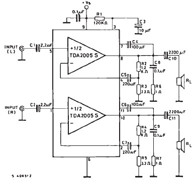
The TDA2005 car audio amplifier circuit is specifically designed for use in devices such as car radios, CD players, and similar equipment. This amplifier is based on the TDA2005 audio integrated circuit (IC), capable of delivering a maximum output...
The signal EncoderBit1 (LOW) is inverted by the hex inverter U5A and then sent to a 4-input AND gate U3A, along with EncoderBit0 (HIGH), the output from a J-K flip-flop (HIGH), and a HIGH signal from Vcc. During a...
The circuit consists of an ultrasonic transmitter and a receiver that operate at the same frequency. Ultrasonic piezoelectric transducers serve as the output and input devices, respectively, with their frequency of operation determined by the specific devices used. The...
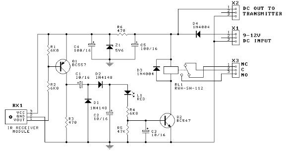
This door minder electronic project is based on a 555 timer circuit and utilizes an infrared (IR) beam to monitor doorways, passageways, or any other designated area. When the IR beam is interrupted, a relay is activated, which can...
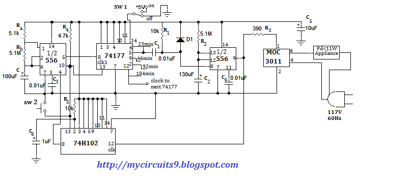
This document presents an electronic project focused on device control using a timer. This circuit allows for the activation of an appliance at a specified time for a predetermined duration. It can be applied to manage the operation of...
The switch control system utilizes sensors to inform the microcontroller of the trains' positions on the layout. This ensures that only one train occupies the main line at any given time and that switches are correctly set for the...
Warning: include(partials/cookie-banner.php): Failed to open stream: Permission denied in /var/www/html/nextgr/view-circuit.php on line 713
Warning: include(): Failed opening 'partials/cookie-banner.php' for inclusion (include_path='.:/usr/share/php') in /var/www/html/nextgr/view-circuit.php on line 713