
12 V Florescent lamp driver circuit
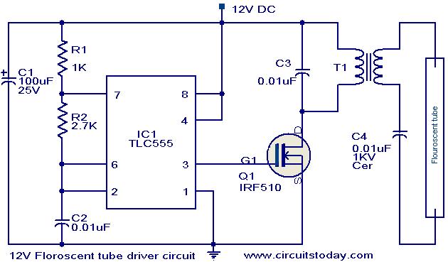
The circuit operates by utilizing the TLC 555 timer IC configured in an astable mode, which continuously switches between high and low states, generating a square wave output. This square wave is fed into the gate of the MOSFET (Q1), which acts as a switch. When the MOSFET is turned on, it allows current to flow through the primary winding of the transformer (T1), inducing a high voltage in the secondary winding due to the transformer's step-up characteristics.
The selection of the transformer is crucial; a 10 W, 230 V to 10 V transformer is specified to ensure that it can handle the power requirements of the fluorescent lamp while providing the necessary voltage increase. The inverted configuration of the transformer ensures that the lower voltage side is connected to the MOSFET, allowing it to control the higher voltage output effectively.
This design is efficient for driving fluorescent lamps, as it minimizes the complexity of the circuit while providing the necessary high voltage required for lamp operation. Proper heat dissipation mechanisms should be considered for the MOSFET, as it may generate heat during operation, and adequate insulation must be ensured to handle the high voltage output safely.Here is a simple and effective circuit for driving florescent lamps from a 12 V supply. The circuit is nothing but consists of an oscillator, a MOSFET switch and a step-up transformer for driving the florescent lamp. The IC1 TLC 555 is wired as an astable multivibrator for producing the necessary oscillations. The MOSFET Q1 is used to amplify the os cillations produced by the IC1. The out put of MOSFET is connected to the primary of the step up transformer to produce a ~400 V AC for driving the florescent lamp. For T1, use a 10W, 230V to10V step down transformer in the inverted configuration. That is 10V winding must be connected to the MOSFET side and 240V winding must be connected to florescent lamp side.
🔗 External reference
Related Circuits

This is a 35.3 to 10.7 MHz converter circuit. It converts the 35.3 MHz signal coming from a VHF/UHF tuner down to an FM tuner to decode the TV audio in FM. The 35.3 to 10.7 MHz converter circuit is...
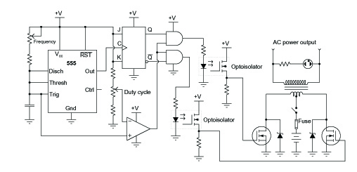
A common topology for DC-AC power converter circuits employs a pair of transistors to switch DC current through the center-tapped winding of a step-up transformer. Examine the check plot images from a PCB drafting program for a control board...
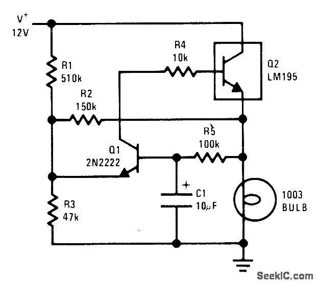
The National LM195 power transistor is activated and deactivated once per second to flash a 12-V lamp. The current limiting feature of the LM195 prevents high peak currents during turn-on, even when a cold lamp can draw up to...
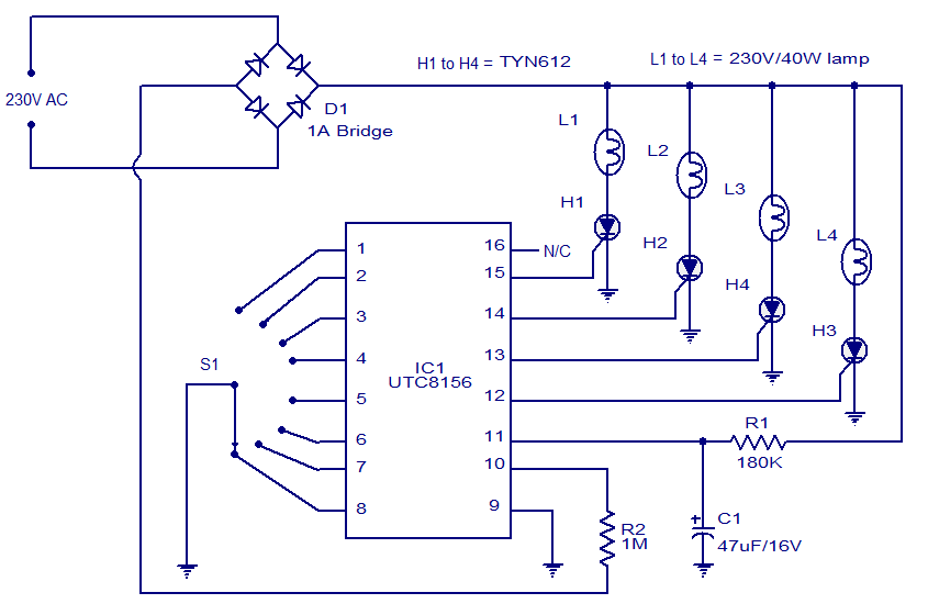
This 8-function serial Christmas lamp controller is based on the IC UTC 8156 from Unisonic. Specifically designed for this purpose, the UTC 8156 can control four lamps in eight modes: waves, sequential, slo-gol, chasing/flash, slow fade, twinkle/flash, steady ON,...
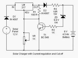
By adjusting the Adjust pin, the output voltage and current can be regulated. A variable resistor (VR) is connected between the Adjust pin and ground to achieve an output voltage of 9 volts to the battery. Resistor R3 limits...
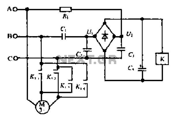
Composition ratio circuit. The circuit consists of resistors and capacitors that form a shift register circuit with diodes VD1 to VD4, creating a bridge for electric current. Capacitor C4 is utilized for filtering applications and for eliminating instantaneous relay...
Warning: include(partials/cookie-banner.php): Failed to open stream: Permission denied in /var/www/html/nextgr/view-circuit.php on line 713
Warning: include(): Failed opening 'partials/cookie-banner.php' for inclusion (include_path='.:/usr/share/php') in /var/www/html/nextgr/view-circuit.php on line 713