
A motor reversing automatic adjustment circuit
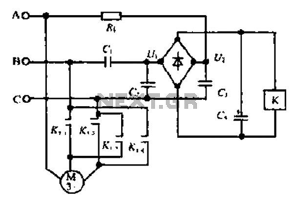
The composition ratio circuit is designed to manage the phase relationships between multiple voltage sources, ensuring proper operation of devices such as motors and relays. The circuit employs a combination of resistors (Ri, R) and capacitors (C, C3, C4) to establish a controlled phase shift. Diodes VD1 to VD4 create a bridge configuration, allowing for efficient current flow while protecting against reverse polarity and ensuring that the operation remains stable under varying load conditions.
Capacitor C4 plays a critical role in filtering out noise and stabilizing the voltage output, which is essential during relay activation. This filtering capability prevents false triggering of the relay, ensuring that the motor operates only when the conditions are suitable. The relationship between the phases is crucial for maintaining the correct sequence of operation; thus, the circuit's design allows for adjustments based on load and phase requirements.
The scaling circuit provides a means to monitor and adjust the voltage levels, where Ui is derived from the three-phase voltage amplitude Um. The calculated voltage U2, based on the impedance Z and capacitance Cp, allows for precise control over the circuit's response to changes in load or supply conditions. The output configuration is designed to facilitate the flow of current through the relay, which subsequently energizes the motor in a predefined sequence (A, B, C).
In the event of a phase alteration, such as switching the wiring for AC at phase B, the circuit's design must account for potential discrepancies in amplitude. This situation could lead to erratic motor behavior, emphasizing the importance of maintaining balanced phase relationships for optimal performance. Overall, this circuit is integral in applications where precise control of motor operation is required, particularly in industrial settings where reliability and efficiency are paramount. C ,. C! Composition ratio circuit. Ri. C, constituting the shift shed circuit diode VDi - VD4 constitute destroy stream bridge, electric pit C4 is used - Application Filtering and elimination of instant relay is energized Mau spy operation. When the phase FF is A - B - C (B .C phase phase phase lag rA rB phase advance) when, U c advance UBc. When cl c-, when seen from the scaling circuit. Ui J/2U s, where Um is the three-phase voltage amplitude. From the phase shift circuit r Ri, c3 constituted, T calculated U2 fYJ voltage amplitude of U! Two (Um/Z)/( C p). To simplify too ! Uln October. :(. 3.j. When I icl 3, the la u2 1 2um, namely ui l zi 2um. and feng bian h bit with, open i) point output hip as i n, current flows through relay 0, kl water moves electrical motor cap sequence is abc.
when wiring to change phase for ac at b .u {.ul, amplitude are not equal, blind trust, chu action, loving rotation of constant.
Related Circuits

A simple touch dimmer circuit diagram using the TT6061 IC, which is a touch control integrated circuit used for light dimmer circuits and lamp dimmer circuits. The touch dimmer circuit utilizing the TT6061 IC is designed to provide a user-friendly...
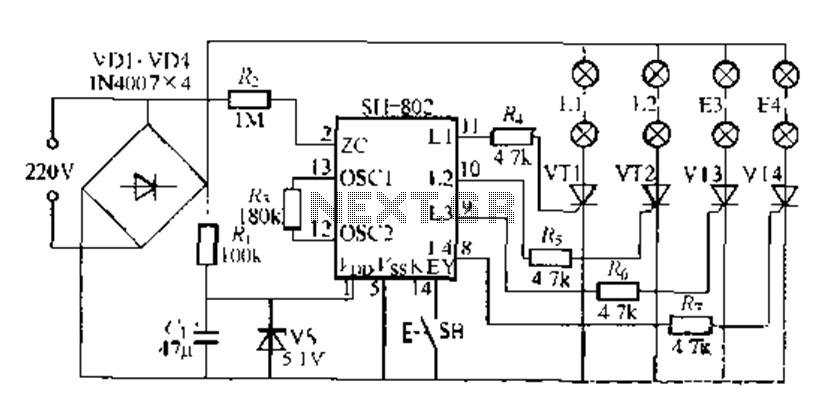
A digital integrated circuit simplifies the response process significantly. The diagram illustrates a circuit comprising four responder groups. The digital integrated circuit described serves as a crucial component in various electronic systems, primarily focusing on enhancing response efficiency. It comprises...
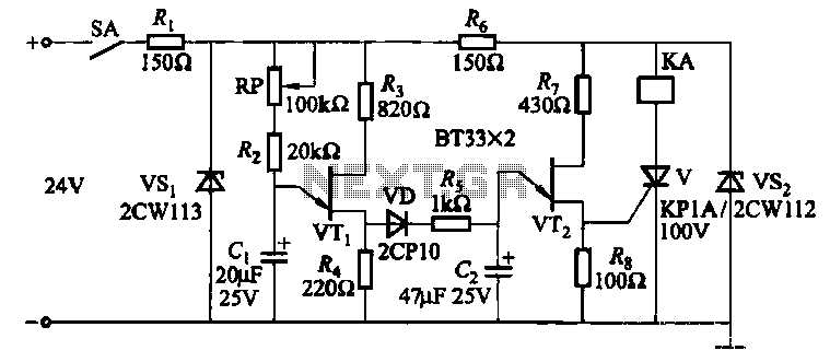
This circuit consists of three single-junction transistor time relay circuits utilizing a pulse charging mechanism, allowing for extended delay times of up to several minutes. The first stage delay circuit incorporates unijunction transistors (VTi) and other components, where capacitor...

This second-order low-pass filter utilizes a 741 operational amplifier and can be tuned from 2.5 kHz to 25 kHz. The circuit is beneficial in audio and tone control applications. R1 and R2 are ganged potentiometers. The described circuit features a...
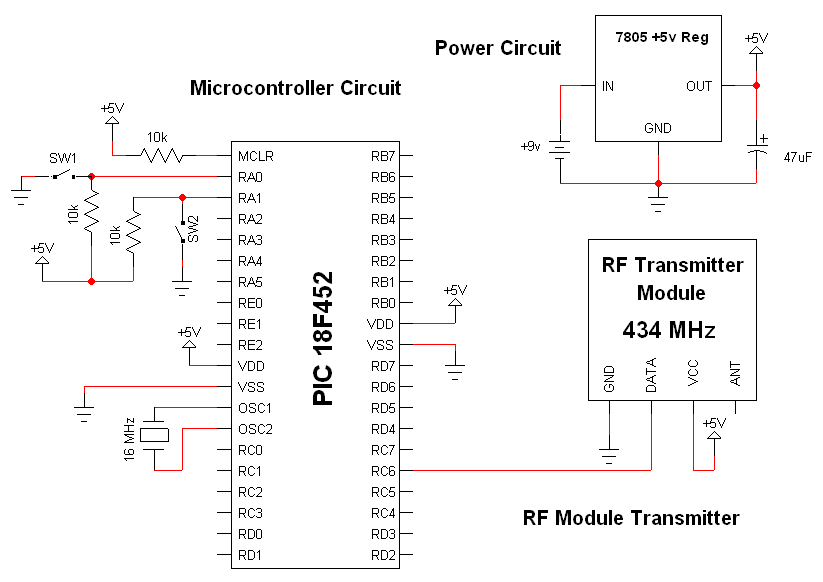
The RF modules utilized in this schematic are straightforward, requiring only a few additional pins for power, ground, and data connections. The primary components featured in this schematic include the RF transmitter module, the RF receiver module, and the...
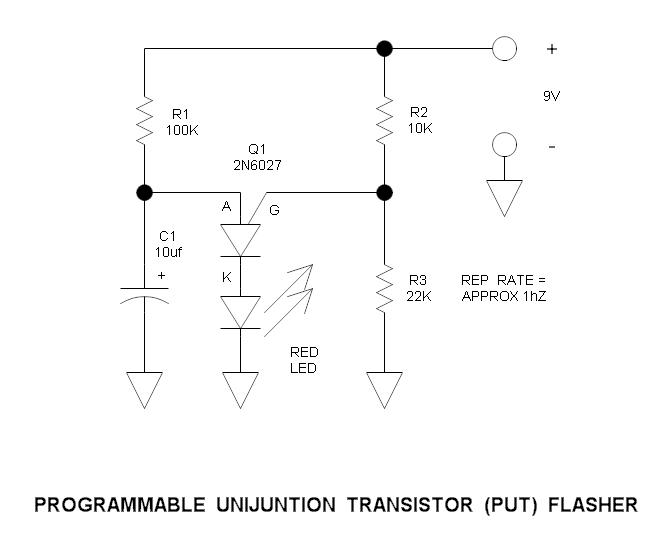
This is a simple circuit that illustrates the function of the programmable unijunction transistor. It can be quickly wired on a proto-board. The circuit utilizes a programmable unijunction transistor (PUT) to demonstrate its operation as an oscillator. The PUT, which...