
12 Volt, 10 Amp Switching Power Supply
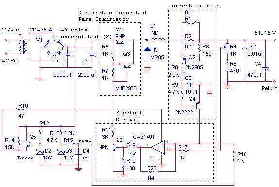
The described switching power supply operates at a nominal output of 12 volts and a maximum current output of 10 amps. It employs a discrete transistor regulator, which is a notable choice for its simplicity and effectiveness in converting input power to the desired output. The inclusion of an operational amplifier (op-amp) as a comparator in the feedback loop is critical for maintaining voltage regulation. This configuration allows the system to compare the output voltage to a reference voltage, adjusting the transistor's conduction to stabilize the output.
The design, dating back to 1984, utilizes a variable frequency approach rather than modern pulse width modulation (PWM) techniques. This can impact efficiency and thermal performance, as variable frequency operation may lead to less optimal switching characteristics compared to PWM methods prevalent in contemporary designs.
The schematic indicates that the front panel power-on indicator light is not depicted, which may be a consideration for user interface design. Furthermore, the absence of an adjustable current limiter suggests that the power supply is intended for applications where a fixed current limit is sufficient. The components R1, R2, R3, Q2, R8, R9, C5, and Q4 collectively establish the current limit at approximately 10 amps, ensuring protection against overcurrent conditions.
Overall, while the design reflects the technology of its time, it demonstrates fundamental principles of power supply design that remain relevant, such as feedback regulation and current limiting. The circuit's simplicity may also contribute to reliability, making it suitable for various applications where precision and stability are required.The switching power supply, shown in the schematic, provides 12 volts, at 10 amps, maximum, using a discrete transistor regulator with an op-amp functioning as a comparator in the feedback circuit. The supply was constructed in 1984 and is variable frequency, as opposed to the pulse width modulator (PWM) controllers used today.
With reference to the schematic, the front panel power-on light is not shown. There is no adjustable current limiter in this unit, although R1, R2, R3, Q2, R8, R9, C5 and Q4 set the current limit to approximately 10 amps. As you can see, the design is ver 🔗 External reference
Related Circuits
The sensitivity of the receiver can be considerably increased if an RF amplifier is placed between the receiver and its aerial. The amplifier circuit does not use resonant circuits, making it suitable for both medium waves and low waves,...
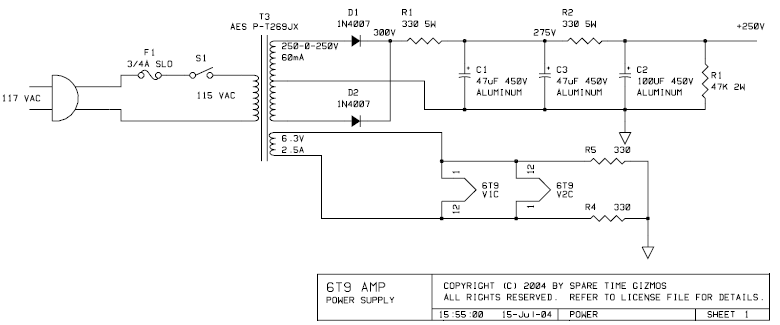
The PCB for this amplifier can be purchased from Spare Time Gizmos for $16 US. In a single afternoon, the entire board can be assembled and placed into a chassis of choice. The value and type of components are...
The 7815 regulates the positive supply, while the 7915 regulates the negative supply. The transformer should have a primary rating of 240/220 volts for Europe or 120 volts for North America. The center-tapped secondary coil should be rated approximately...
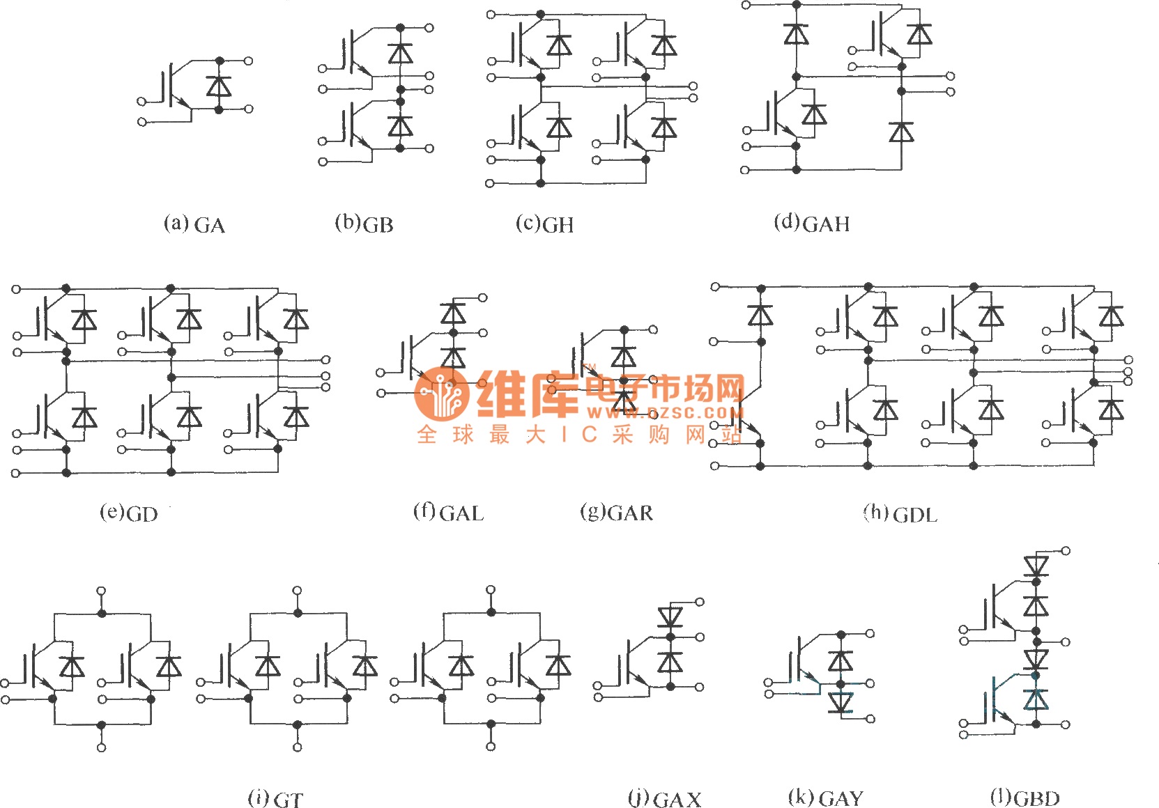
This document describes various electronic modules, including: (a) a single switch module; (b) a two-unit half bridge module; (c) an H bridge (single-phase bridge) module; (d) an asymmetrical H bridge module; (e) a three-phase bridge (six-unit or inverter bridge)...
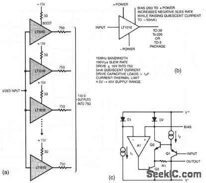
The resistors in the output lines are used to isolate reflections from unterminated lines. If the line characteristics are known, the resistors can be removed. To satisfy NTSC gain-phase requirements, a small-value boost resistor is employed. Figures 3-27B and...

This is a simple nickel-cadmium (NiCd) battery charger powered by solar cells. A solar cell panel or an array of solar cells can charge a battery at more than 80% efficiency, provided the available voltage exceeds the fully charged...
Warning: include(partials/cookie-banner.php): Failed to open stream: Permission denied in /var/www/html/nextgr/view-circuit.php on line 713
Warning: include(): Failed opening 'partials/cookie-banner.php' for inclusion (include_path='.:/usr/share/php') in /var/www/html/nextgr/view-circuit.php on line 713