
Dual Regulated Power Supply

The circuit described utilizes the 7815 and 7915 voltage regulators, which are designed to provide stable output voltages of +15V and -15V, respectively. These regulators are essential components in applications where a dual-polarity power supply is required, such as operational amplifier circuits or analog signal processing.
The transformer is a critical element in this setup. It should be selected based on the geographical voltage supply: either a 240/220V primary for European use or a 120V primary for North American use. The center-tapped secondary coil is designed to deliver approximately 18 volts AC, which is converted to the desired DC output voltage by the regulators. The 1 amp rating of the secondary coil is essential to ensure that there is sufficient current available to meet the demands of the load while also accounting for voltage drops across the regulators.
In the circuit, the output from the center-tapped transformer is fed into the input terminals of the 7815 and 7915 regulators. Each regulator will require appropriate input and output capacitors to stabilize the voltage and filter out any noise. Typically, a 0.33 µF capacitor is placed at the input of each regulator, while a 0.1 µF capacitor is placed at the output to improve transient response and stability.
The output of the 7815 will provide a steady +15V supply, while the output from the 7915 will provide a steady -15V supply. Both outputs can be utilized simultaneously to power various electronic devices that require dual polarity.
To ensure safety and efficiency, it is advisable to incorporate a fuse in the primary circuit to protect against overload conditions. Additionally, heat sinks may be required for the voltage regulators, as they can dissipate significant heat during operation, particularly under high load conditions. The overall design should also consider proper grounding techniques to minimize noise and ensure reliable operation of the power supply circuit.
This configuration is widely used in laboratory settings and for powering low to moderate current electronic projects, making it a versatile solution for various applications in electronics.The 7815 regulatates the positive supply, and the 7915 regulates the negative supply. The transformer should have a primary rating of 240/220 volts for europe, or 120 volts for North America. The centre tapped secondary coil should be rated about 18 volts at 1 amp or higher, allowing for losses in the regulator.
An application for this type of circuit would be for a small regulated bench power supply. 🔗 External reference
Related Circuits
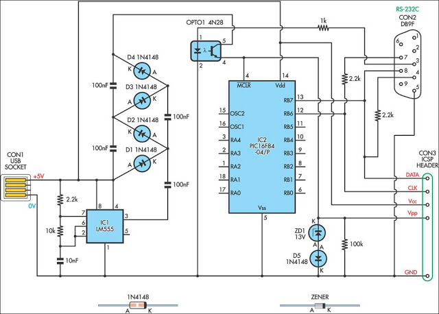
This simple circuit can be used to program the PIC16F84 and similar flash memory type parts. It uses a cheap 555 timer IC to generate the programming voltage. The circuit utilizes a 555 timer IC configured in astable mode to...
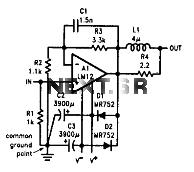
Output-clamp diodes are essential due to the inductive nature of loudspeakers. Output LR isolation is employed as audio amplifiers are typically designed to manage load capacitance of up to 2 µF. Large supply-bypass capacitors placed near the integrated circuit...
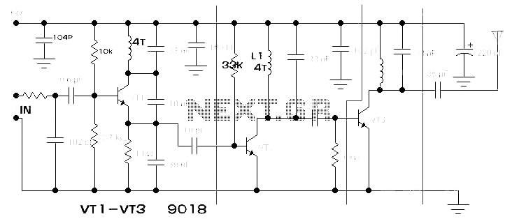
The components available were utilized to create a long-range FM radio transmitter operating within the 88-108 MHz band, designed for playing music. The circuit includes a power section that rectifies mains voltage to provide a stable 12V DC for...
The LM317 is capable of providing extremely good load regulation, but a few precautions are needed to obtain maximum performance. For best performance, the programming resistor (R1) should be connected as close to the regulator as possible to minimize...
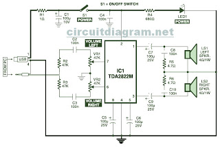
This is the circuit diagram of a USB-powered computer speaker, commonly referred to as multimedia speakers for PCs. The circuit features a single-chip design, operates on a low-voltage electrical power supply, is compatible with USB power from computers, and...
The amp was called "El Cheapo 2-30", and was rated at a maximum of 30W per channel into 16 Ohms. It used a single regulated power supply and capacitor coupled speaker. Having a scan of the original, the exact circuit...