
12 Volt 30 Amp Power Supply
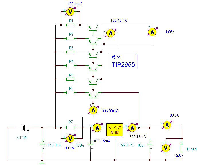
The circuit design incorporates a 7812 voltage regulator, which is known for its ability to maintain a stable output voltage of 12 volts. The 7812 IC is capable of handling moderate current loads; however, to achieve higher output currents, external pass transistors are employed. This configuration allows for increased current handling capacity while maintaining the voltage regulation characteristics of the 7812.
In this setup, the 7812 serves as the primary voltage reference and control element. The output from the 7812 is connected to the bases of the external pass transistors, which are configured in a current amplification arrangement. These pass transistors can be NPN or PNP types, depending on the design requirements and load characteristics.
The circuit should include adequate heat sinking for both the 7812 IC and the pass transistors, as they will dissipate significant power during operation, especially under high load conditions. The thermal management is critical to ensure reliable performance and prevent thermal shutdown or damage to the components.
Additionally, proper bypass capacitors should be placed at the input and output of the 7812 regulator to filter out noise and ensure stable operation. A larger capacitor may also be placed at the output to handle transient load changes effectively.
Overall, this design approach provides an efficient and robust solution for applications requiring substantial current at a regulated 12V output, making it suitable for various electronic projects and power supply needs.Using a single 7812 IC voltage regulator and multiple outboard pass transistors, this power supply can deliver output load currents of up to 30 amps.. 🔗 External reference
Related Circuits
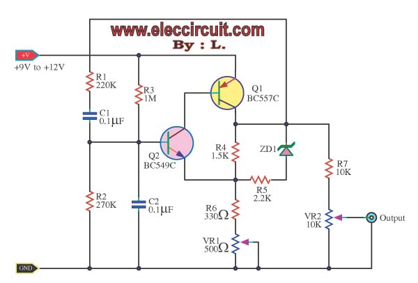
In a sine wave oscillator circuit, a thermistor and an incandescent lamp are often utilized to stabilize the output of the circuit at a fixed value. The resistance of... The sine wave oscillator circuit is designed to generate a continuous...
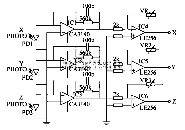
A semiconductor color sensor is designed to identify the color of an object using three photodiodes (PD1, PD2, PD3) and three corresponding color filters (X-PHOTO, Y-PHOTO, Z-PHOTO). Each photodiode is paired with a specific color filter: red (R), green...
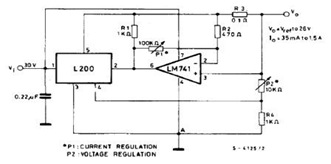
The datasheet contains application circuit diagrams for the L200, including a Programmable Voltage Regulator, a High Current Voltage Regulator with Short Circuit Protection, a Digitally Selected Regulator with Inhibit, a Programmable Voltage and Current Regulator, a High Current Regulator...
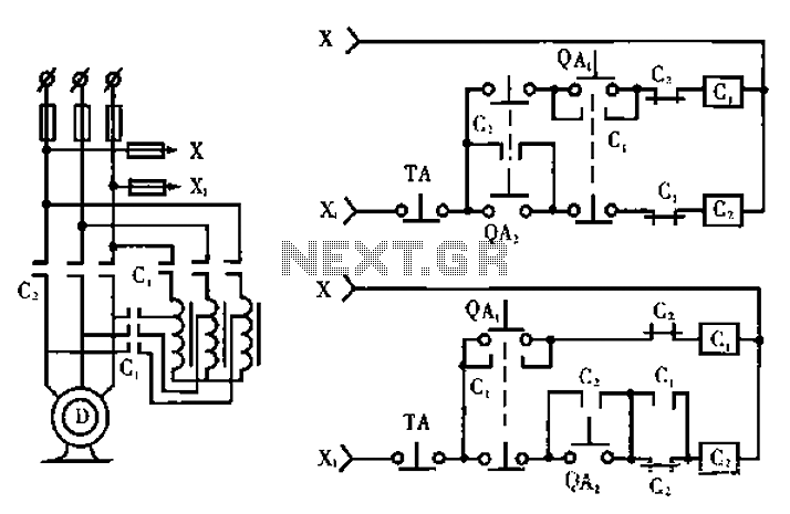
The circuit operates with relevant components highlighted in the manual's draw mode. Figure A presents a circuit schematic, while Figure B illustrates a typical conventional secondary circuit layout. Figure E showcases an improved secondary circuit schematic diagram that incorporates...
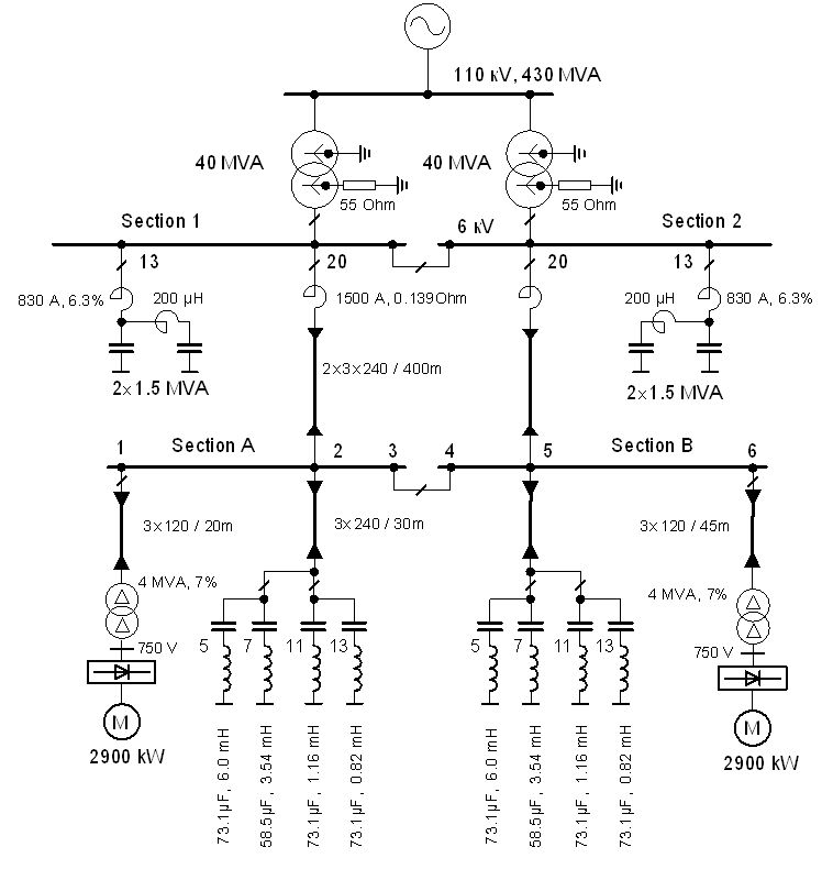
The vertical line indicates the instance of the 5th harmonic filter connection. The diagram illustrates the power system with the designed group of single-tuned filters for a system with a DC drive supplied by a 6-pulse controlled rectifier: PN...
A project involves two distance sensors that signal an Arduino to operate a servo motor when an object comes within range. The system functions correctly; however, the sensors output a consistently high voltage, necessitating a high cutoff voltage in...
Warning: include(partials/cookie-banner.php): Failed to open stream: Permission denied in /var/www/html/nextgr/view-circuit.php on line 713
Warning: include(): Failed opening 'partials/cookie-banner.php' for inclusion (include_path='.:/usr/share/php') in /var/www/html/nextgr/view-circuit.php on line 713