
High-power motor control circuit summary
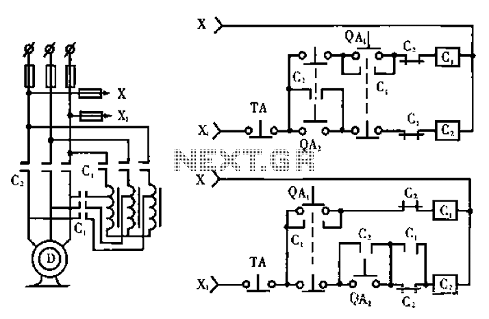
The schematic circuit design presented in Figure C incorporates several protective features aimed at enhancing operational safety and reliability. The circuit utilizes a combination of relays, timers, and interlocks to ensure that the device only starts under the correct conditions.
The circuit begins with the QAz start button, which is connected to a relay that only energizes if certain preconditions are met. This includes checks for the operational state of the machine and the status of other safety interlocks. If these conditions are satisfied, the relay activates, allowing current to flow through the main contactor C, which then engages the motor or load.
To prevent accidental engagement, the circuit includes a delay timer that ensures the motor does not start immediately upon pressing the start button. This delay allows operators to confirm that all safety measures are in place before the machine begins operation. Additionally, the design features a stop button that can interrupt the power supply to the relay, ensuring that the machine can be safely deactivated at any time.
Furthermore, the circuit employs overload protection mechanisms, which monitor the current draw of the motor. If the current exceeds a predefined threshold, the overload relay will trip, disconnecting power to the motor and preventing damage. This feature is crucial in maintaining the longevity of the equipment and ensuring safe operation.
In summary, the circuit design shown in Figure C not only improves upon the conventional secondary circuit by incorporating mandatory safety features but also addresses the potential risks associated with operator error. By implementing these enhancements, the circuit ensures a more reliable and safer operational environment for electrical devices. Circuit works (only the relevant parts of the manual draw mode): Figure a shows a circuit schematic circuit; Fig. B Typical electricity as conventional secondary circuit road; Fig e shows the improved, with the mandatory nature of the program secondary circuit schematic diagram. Firstly deficiencies of conventional secondary circuit, the circuit in Figure b form, it seems perfectly reasonable, it works we are all familiar.
However, many operators, the quality varies, assuming that the operator of a small mistake by running the button to start the device. B from FIG principle, the press QAz run button, so the device is based on the procedure after the first press starts running through QA, start button, but more than misuse, can make the run contactor C: pull into the work state, becoming a direct start, this time starting current cause great damage to the equipment.
For this reason we designed the circuit shown in Figure c, before it can completely prevent the occurrence of accidents.
Related Circuits

These two schematics are variations on another PWM circuit that I designed. The diagrams are for 12V operation only and there are high side (common ground) and low side (common +12V) versions. The low side version of the circuit...

The circuit is designed for model airplanes, boats, and cars that utilize glow plugs for their miniature internal combustion engines (ranging from 0.1cc to 15cc). These engines are equipped with heavy batteries, high-tension coils, and capacitors necessary for classic...
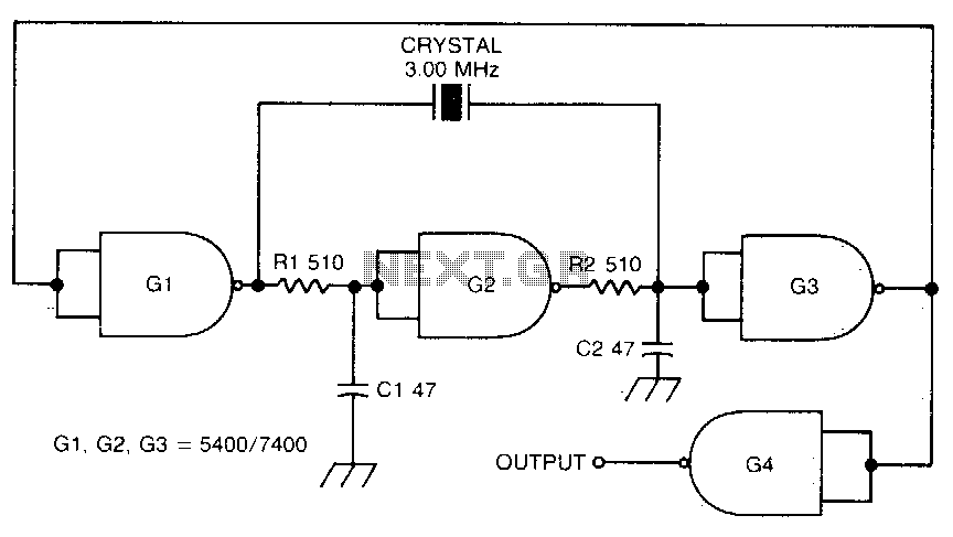
This circuit oscillates without the crystal. When the crystal is included in the circuit, the frequency will match that of the crystal. The circuit exhibits good starting characteristics even with low-quality crystals. This circuit design features a basic oscillator configuration...
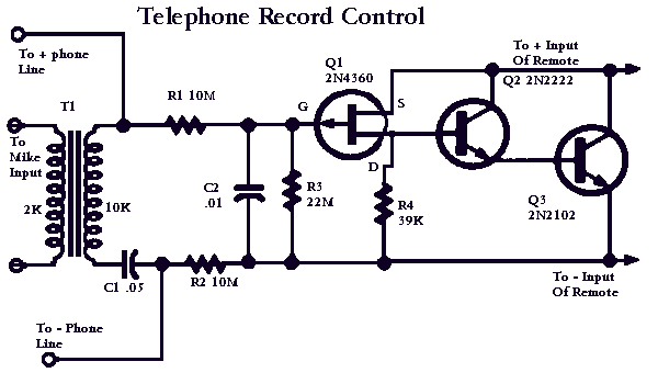
This circuit will allow you to connect any tape recorder that has a mic and remote input to a phone line and automatically record both sides of a conversation whenever the phone is in use. You will need to...
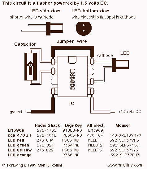
This project uses a 3909 IC and a few other parts; power is 1.5 volts DC. The project employs the 3909 integrated circuit (IC), which is a versatile component commonly used in various electronic applications, particularly in timer and oscillator...

This electronic RF detector project is constructed using common transistors and a few standard electronic components. The RF detector is capable of responding to RF signals below the standard broadcast band and extending to over 500 MHz, providing both...