
12 Volt Car Battery Charger Circuit Schematic
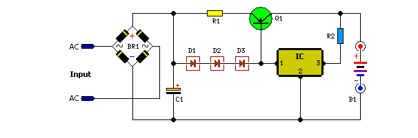
This battery charger is designed to operate with a continuous charging mechanism, maintaining the maximum current output throughout the majority of the charging cycle. As the battery approaches its full voltage capacity, the charging current gradually decreases, a process known as "tapering off." This method is beneficial for ensuring that the battery receives an adequate charge without the risk of overcharging, which can lead to battery damage or reduced lifespan.
The circuit typically consists of several key components, including a power supply, a current regulation module, and a voltage sensing circuit. The power supply provides the necessary voltage and current to begin the charging process. The current regulation module ensures that the output current remains at the maximum allowable level for the battery being charged, which is critical for efficient charging.
As the battery voltage rises, the voltage sensing circuit continuously monitors the battery's voltage level. Once the voltage reaches a predetermined threshold, the current regulation module begins to reduce the output current. This tapering effect helps to prevent excessive heat generation within the battery and enhances safety during the charging process.
The charger may also include additional features such as temperature compensation, which adjusts the charging parameters based on the battery temperature to optimize performance and safety. Furthermore, an LED indicator may be integrated into the design to provide visual feedback on the charging status, indicating when the battery is charging, fully charged, or if there is an error in the charging process.
Overall, this battery charger design emphasizes efficiency and safety, making it suitable for various applications where reliable battery charging is essential.Unlike many units, this battery charger continuously charges at maximum current, tapering off only near full battery voltage. In this unit, the full load.. 🔗 External reference
Related Circuits
This page provides information on circuits that can trigger stroboscopes from external circuits. The circuits are designed to be integrated into stroboscope systems, allowing them to be activated using an external trigger pulse. The standard trigger pulse utilized in...

This alarm is designed to activate its siren only once. When the alarm is triggered, the siren will sound for a predetermined duration before automatically turning off and remaining inactive. The alarm system features a single zone with independently...
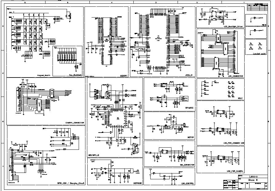
General use camera backlighting baseband circuit: the circuit includes a table of contents, Calyso, iota, matrix, keypad key, memory, IC image, LCD connector, LCD backlight driver, locate points, holes, Speaker4, camera connector, motor, MIDI/MP3 ICs, charging circuit, microphone phone,...

This is a design circuit for a low-cost FM antenna booster that can be used to listen to programs from distant FM stations clearly. The antenna FM booster circuit comprises a common-emitter tuned RF preamplifier wired around the VHF/UHF...

This switch utilizes four CD4013BE dual flip-flops, an inverter, and an optoisolator to control a triac, allowing it to switch a 25-A AC load current. A standard 4x3 telephone keypad is employed for entering a 6-digit code. In the...
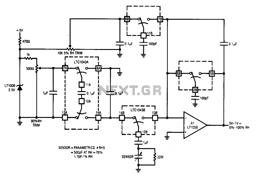
This circuit integrates two LTC1043 devices with a humidity transducer based on a charge-pump configuration. The specified sensor has a nominal capacitance of 400 pF at a relative humidity (RH) of 76%, exhibiting a slope of 1.7 pF/% RH....
Warning: include(partials/cookie-banner.php): Failed to open stream: Permission denied in /var/www/html/nextgr/view-circuit.php on line 713
Warning: include(): Failed opening 'partials/cookie-banner.php' for inclusion (include_path='.:/usr/share/php') in /var/www/html/nextgr/view-circuit.php on line 713