
Trigger circuits for stroboscopes
The design of the triggering circuit for stroboscopes emphasizes safety and reliability, particularly due to the high voltages involved in stroboscope operation. The use of optoisolators, such as the MOC3023, effectively separates the low-voltage control circuit from the high-voltage stroboscope circuitry, mitigating the risk of electric shock. Additionally, employing transformer isolation further enhances safety by ensuring that the trigger signal remains isolated from the high-voltage components.
The implementation of a 470-ohm resistor in series with the pulse transformer serves a dual purpose: it limits the current to safe levels while ensuring that the trigger pulse is sufficient to activate the TRIAC. This careful consideration of component selection and circuit configuration allows for the reliable triggering of stroboscopes in various applications, whether in custom-built controllers or modifications to existing stroboscope designs.
Overall, the described circuit offers a robust solution for integrating external triggering capabilities into stroboscope systems, with a strong emphasis on maintaining safety through effective isolation techniques. The choice of components and their ratings plays a critical role in achieving consistent performance while safeguarding against the dangers associated with high-voltage stroboscope operation.This page contains some information on circuits which can be used for triggering stroboscopes from external circuits. The circuit here are designed to be integrate to strboscope circuits so that they can triggered using external trigger pulse.
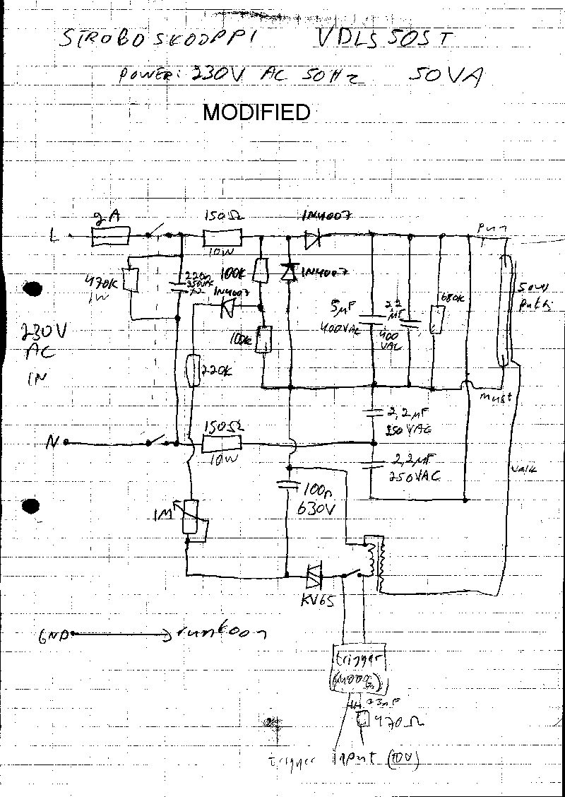
The standard trigger pulse used in professional stroboscope controllers is 3-10V pulse. If you don`t alre ady have a suitable controller, you can built one based on my stroboscope controller design. Stroboscope circuit use lethal voltages, so you must be very careful when operating with them. When the stroboscopes are triggered using an external signal, then there are some extra safety things to consider. The safest way is to provide a complete galvanic isolation of few kV between the trigger input and the stroboscope circuitry.
This isolation can be done using and optoisolator or transformer isolation. CAUTION - high voltage of strobes can cause a nasty and possibly fatal shock. The energy storage capacitor can retain dangerous high voltage after power is removed from the board. This circuit takes 10V trigger pulse to trigger a triac which connect the points A and B together. This circuit can be placed to almost any stroboscope circuit in place of the trigger switch or the trigger triac.
Using this circuit a short pulse applied to the input of MOC3023 will trigger the stroboscope one. If the input of MOC3023 is kept constantly at +10V, the stroboscope keeps triggering constantly at it`s maximum rate, because the circuit retriggers every time when the voltage over TRIAC exceeds around 90V. The isolation between the trigger signal and the stroboscope circuit is provided by MOC3023 optoisolator, which can withstand pulsed up to 7500V.
This isolation level is more than dequate in typical applications. If you want really anjoy this kind of high voltage isolation you must keep in mind to keep enough clearance in the circuit board between the input and output pins of the MOC3023 optoisolator. Another option to provide the isolation between trigger signal and the stroboscope is to use transformer isolation.
In this approach the trigger pulse is fed to the gate of the TRIAC or thyristor though a transformer. There are amny types of transformers which can be used, but the best selection for those would be a pulse transformer which is designed for triggering triacs and provides the necessary isolation levels (at least few kV).
I have used this kind of circuits in triggering some of my stroboscope designs. I have used various types of TRIACs and transformers for implementing this signal. Because the input of a typical pulse transformer is low resistance, I have put a 470 ohm resistor in series with the pulse transformer promary to limit the current which flows to this circuit. Using the 470 ohm resistor, the current using 10V input signal is in oder of 20 mA. When the input resistance is 470 ohms, a tpyical strobo controller can easily trigger few of this kind of circuits.
If you are modifying an actual stroboscope light, my 12V strobocope circuit will give you some idea how to use a transformer isolated trigger circuit in a real stroboscope circuit. The typical voltages applied to the trigger transformers in typical triac circuits are in order of 100-300V.
This means that you have to select a TRIAC which can handle at least 400V voltage. I don`t know what is the minimum rating of the triac suitable for the triggering circuit, but I have had very good results with the TRIACs which can handle at least few amperes of continuous current. It is also a good idea to select a sensitive gate TRIAC so you can trigger the TRIACs reliabily with the low currents available in the circuits described above.
Kemo Electronics makes a module M006 which is ment to be single channel 1000W light organ for light powered with 23V AC. That module is packed to a matchbox size plastic box and has a trigger and audio signal isolation transformer in it.
Besides be 🔗 External reference
Related Circuits

AN79 Linear Technology AN79 modifies methods presented in AN74, allowing for the verification of 30 nanosecond amplifier settling times with 0.1% resolution. The sampling-based technique used is detailed, and results are presented. Appendices cover oscilloscope overdrive issues, the construction...

The 555 Astable generates a clock for this circuit, functioning as an oscillator that produces a square wave output at pin 3. This output is counted by the CD4017 decade counter, which creates a running lights effect. The CD4017...

The LED flasher circuits below operate on a single 1.5 volt battery. The circuit on the upper right uses the popular LM3909 LED flasher IC and requires only a timing capacitor and LED. The top left circuit, designed by...

The MC74HC4538A features a pinout identical to that of the MC14538B. Its inputs are compatible with standard CMOS outputs and, when used with pull-up resistors, they are also compatible with LSTTL outputs. This device operates as a dual monostable...

A high-quality preamplifier with tone controls consisting of three circuits. The NE5532 is chosen as the main integrated circuit due to its ultra-low noise properties, making it a popular choice in fine audio applications. Although these circuits are older...
Construct the circuit and measure the voltage drops across each component using an AC voltmeter. Additionally, measure the total (supply) voltage with the same voltmeter. It will be observed that the individual voltage drops do not sum up to...