
How To Build A One-Time-Only >> Burglar Alarm Circuit
The alarm circuit is structured around a microcontroller or a dedicated alarm IC that manages the activation and timing of the siren. Input from various sensors is processed through a series of comparators and logic gates to determine if an alarm condition has been met. The system includes a power supply circuit to ensure stable operation, typically using a battery backup to maintain functionality during power outages.
The user interface is facilitated through a keypad or a series of switches, allowing for easy programming of exit and entry delays, as well as the activation of different zones. Visual indicators, such as LEDs, provide real-time feedback on the system's status, including operational readiness and fault conditions.
The expansion modules are connected via a bus system, enabling easy integration of additional zones without significant modifications to the base circuit. Each zone is monitored continuously, and any fault detected will interrupt the arming sequence, ensuring that the system remains secure at all times.
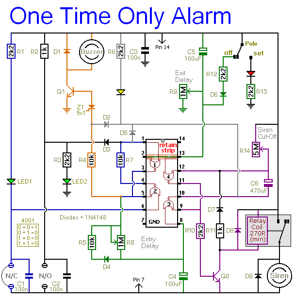
In summary, this alarm system is designed for reliability and ease of use, featuring a robust architecture that allows for scalability and adaptability to various security needs. The careful selection of components and configuration parameters ensures that the system can be tailored to specific environments while maintaining high levels of security.This alarm is designed to sound its Siren only once. That is - when the alarm is activated - the Siren will sound for a preset length of time. Then it will switch off and remain off. The alarm will not re-activate. The basic alarm has a single zone with independently adjustable Exit and Entry delays. The zone will accommodate the usual types of no rmally-open and normally-closed input devices - such as pressure mats, magnetic-reed contacts, micro switches, foil tape and PIRs. A range of Expansion Modules allow you to add any number of Instant Alarm Zones, Personal Attack Zones and Tamper Zones to your system.
There`s also an Untimed Output Module. It will keep an internal sounder, strobe-light, lamp or whatever going after the siren has stopped. The alarm may be operated by a simple hidden two-way switch - such as a light switch. If you want more security - you can use a key switch - or one of a number of code operated Keypad Switches. Before you set the alarm - make sure that the building is secure - that ALL of the Green LEDs are lighting - and that the Yellow LED is off.
If the Yellow LED is lighting - there`s a fault in one of the zones - and THE ALARM WILL NOT SET. Depending on the setting of R9 - when you move Sw1 to the "set" position - you have up to about a minute to leave the building. When you return and open the door - the Buzzer will sound. Depending on the setting of R8 - you have up to about a minute to switch the alarm off. If you fail to do so - the Siren will sound. Depending on the setting of R14 - the Siren will sound for up to about 20-minutes. Then it will switch off - and remain off. Of course - you can stop the noise at any time by moving Sw1 to the "off" position. 🔗 External reference
Related Circuits

A temperature-controlled pulse-width-modulator (PWM) boost converter circuit diagram is illustrated in the following figure. This boost converter is designed to operate a 12V fan using a 5V supply while maintaining temperature control. The temperature-controlled PWM boost converter circuit operates by...
In pulse position modulation, the amplitude and width of the pulses are kept constant, while the position of each pulse with reference to the position of the reference pulse is changed according to the instantaneous sampled value of the...
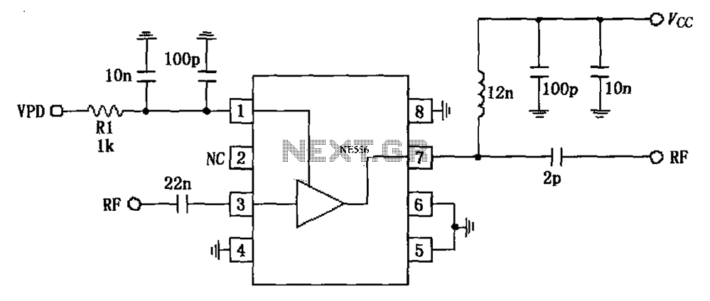
The circuit is based on an 880 MHz RF2347 low noise amplifier application. The radio frequency (RF) signal enters through input pin 3, and after amplification, the output is available at pin 7. The amplifier is directly coupled to...

This design concept outlines a 12-V DC to 5-V DC (±5%) switched-mode power supply (SMPS). The supply utilizes a 12-V input derived from an array of four 3-V DC, 40-mA solar cells connected in series. The proposed switched-mode power supply...
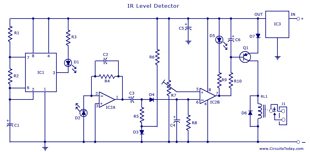
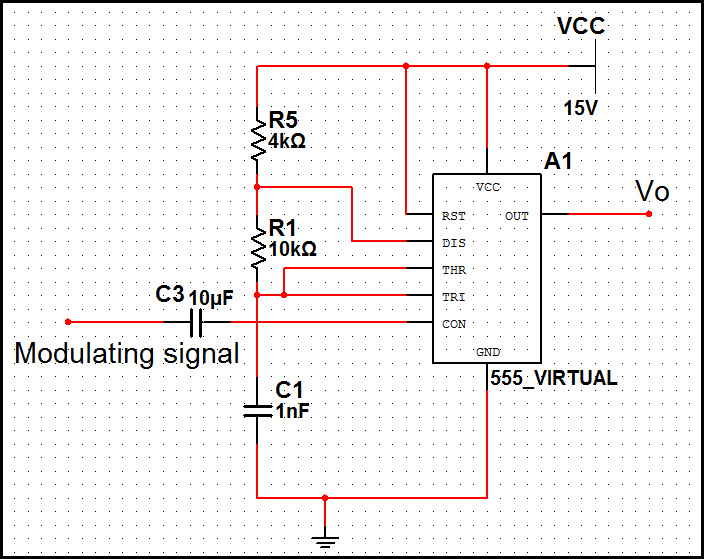
An infrared (IR) sensor or detector circuit diagram utilizing a 555 integrated circuit (IC), primarily employed as a water level or liquid level sensor and proximity detector circuit. The described circuit employs a 555 timer IC configured in a monostable...

The use of a differential capacitor enables temperature compensation in an LC circuit utilizing an NFO and N1500 ceramic. C6 serves as a differential capacitor featuring two stators and one common rotor. When one stator's capacitance reaches its maximum...
Warning: include(partials/cookie-banner.php): Failed to open stream: Permission denied in /var/www/html/nextgr/view-circuit.php on line 713
Warning: include(): Failed opening 'partials/cookie-banner.php' for inclusion (include_path='.:/usr/share/php') in /var/www/html/nextgr/view-circuit.php on line 713