
humidity sensor circuit
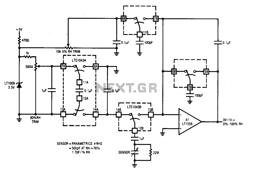
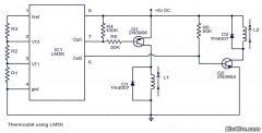
This circuit is designed to accurately measure humidity levels by utilizing the characteristics of the LTC1043 integrated circuits, which are precision analog switches. The LTC1043A performs the function of inverting the reference voltage supplied by the LT1009, ensuring that the humidity sensor operates under a controlled negative voltage. This is crucial for maintaining sensor integrity and preventing electrochemical degradation over time.
The humidity sensor's capacitance is sensitive to changes in relative humidity, allowing for precise readings. The nominal capacitance of 400 pF at 76% RH means that as the humidity increases or decreases, the capacitance will change accordingly, following the slope of 1.7 pF/% RH. This relationship allows the circuit to convert changes in capacitance into measurable voltage changes.
The LTC1043B plays a vital role in the charge-pump operation by alternating between charging and discharging the humidity sensor. The use of pins 12B, 13B, and 14B facilitates the management of the sensor's charge state, ensuring that it is adequately charged to the negative potential established by the LTC1043A. The 1 µF capacitor acts as a coupling element, enabling effective charge transfer to the sensor while maintaining the necessary voltage conditions.
Overall, this circuit design exemplifies a robust approach to humidity sensing, leveraging precision components to ensure accurate and reliable performance.This circuit combines two LTC1043s with a based humidity transducer in a simple charge-pump based circuit. The sensor specified has a nominal 400 pF capacitance at RH = 76%, with a slope of 1.7 pF/% RH. The average voltage across this device must be zero. This provision prevents deleterious electrochemical migration in the sensor. The LTC1043A inverts a resistively scaled portion of the LT1009 reference, generating a negative potential at pin 14A.
The LTC1043B alternately charges and discharges the humidity sensor via pins 12B, 13B, and 14B. With 14B and 12 connected, the sensor charges via the 1 ^F unit to the negative potential at pin 14A. 🔗 External reference
Related Circuits
An adaptable siren generator circuit with multiple applications is presented. It is based on a 556 twin-timer chip, IC1. One timer section generates an audio tone that is directly coupled to the driver transistor, TR1. The other half of...
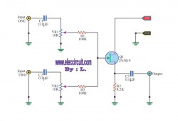
This circuit is a simple mixer circuit that can mix two signal channels into one output channel. It utilizes a codec circuit to convert stereo audio into mono audio. Additionally, the circuit can increase the number of channels by...
The image depicts a proximity switch circuit that includes the HMC1001 Hall effect sensor, an operational amplifier (AMP04), and a light-emitting diode (LED). In this configuration, the operational amplifier functions as a comparator. When a magnet with a length...
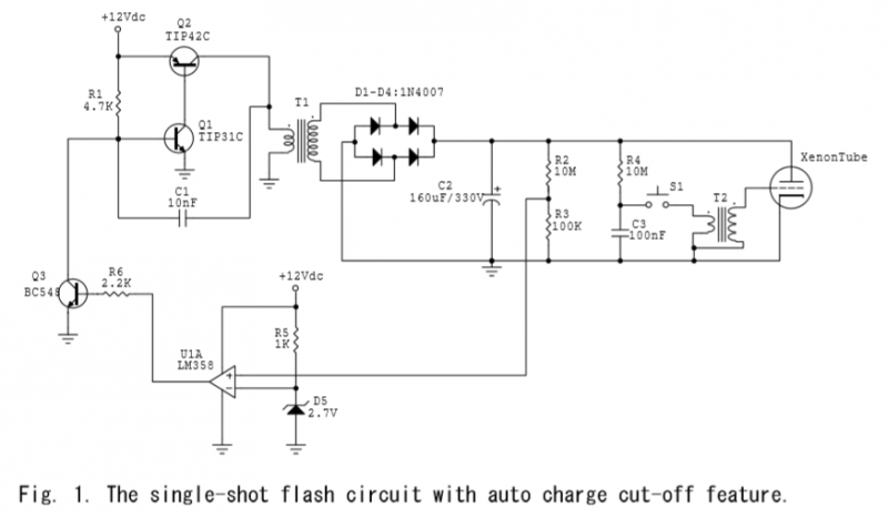
A voltage divider is created using resistors R2 (10MΩ) and R3 (100KΩ), which effectively reduces the voltage across capacitor C2 by a factor of approximately 100. The ground of C2 is connected to the inverter ground for reference. An...
Circuit stereo TDA2822 audio power amplifier circuit schematics. In this series, the TDA2822M IC is utilized as the primary amplifier. Additionally, alternatives such as KA2209 and NJM2073 can also be employed. The TDA2822 audio power amplifier circuit is designed to...
This circuit will allow you to connect any tape recorder that has a mic and remote input to a phone line and automatically record both sides of a conversation whenever the phone is in use. You will need to...