
12 Volt DC Fan Temperature Control
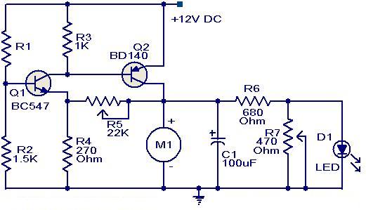
This circuit employs a simple yet effective design to modulate the speed of a DC fan in response to temperature changes using a thermistor as the sensing element. The thermistor, which is a temperature-sensitive resistor, alters its resistance based on the ambient temperature. In this configuration, as the temperature rises, the resistance of the thermistor decreases, leading to an increase in current flow through it.
The first transistor, Q1 (BC 547), is configured as a common-emitter amplifier. When the thermistor detects a rise in temperature, it allows more current to flow into the base of Q1. This increase in base current causes Q1 to conduct more heavily, which subsequently lowers the collector voltage of Q1. The collector of Q1 is connected to the base of the second transistor, Q2 (BD 140), which is configured to drive the fan.
As the collector voltage of Q1 decreases, it provides a stronger bias to the base of Q2, allowing it to conduct more current. This increase in current through Q2 effectively raises the voltage supplied to the fan, thus increasing its speed. The fan operates at a higher speed in response to higher temperatures, providing effective cooling as needed.
Additionally, an LED can be incorporated into the circuit to visually indicate the fan speed. The LED brightness will vary in accordance with the fan speed, providing a simple and effective feedback mechanism to the user. The circuit can be further enhanced by including a potentiometer to adjust the sensitivity of the thermistor or by adding a heat sink to the transistors to improve thermal management. Overall, this circuit represents a practical solution for temperature-controlled fan speed regulation, suitable for various applications where thermal management is essential.Here is a simple circuit based on two transistors that can be acclimated to ascendancy the acceleration of a 12 V DC fan depending on the temperature. A thermistor (R1) is acclimated to faculty the temperature. When the temperature increases the abject accepted of Q1 (BC 547) increases which in about-face decreases the beneficiary voltage of the af
orementioned transistor. Since the beneficiary of Q1 is accompanying to the abject of Q2 (BD 140), the abatement in beneficiary voltage of Q1 advanced biases the Q2 added and so do the acceleration of the motor. Also, the accuracy of the LED will be proportional to the acceleration of the motor. 🔗 External reference
Related Circuits
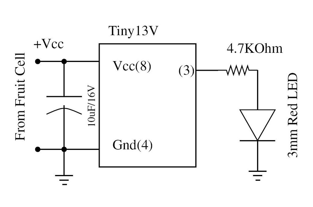
Wire the circuit diagram shown here on a breadboard. The choice of V type of AVR is important. For example, Tiny13V is very appropriate for such an application. To successfully implement the circuit diagram on a breadboard, several considerations must...
At high frequencies, the capacitor Cz can be considered a short circuit (i.e., the resistance of the RPi is negligible). This is illustrated in Figure 4-6 (a) of the apparatus, which corresponds to the equivalent circuit shown in Figure...
For those who labvoeding built and flow of tension and a leader in providing circuit below was developed. If meter is a moving-coil meter 100?A useful. You have to make yourself a new scale. Also useful is a moving...
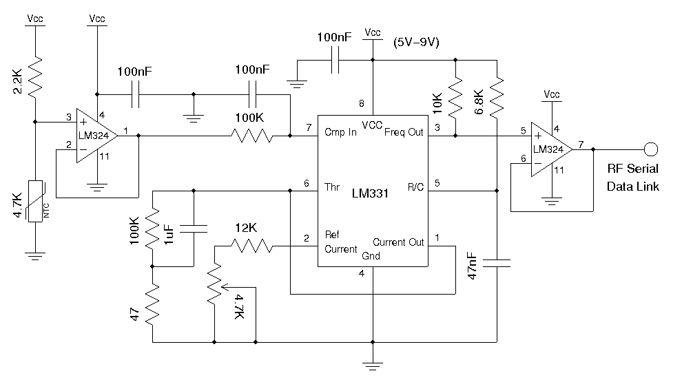
A voltage-to-frequency conversion chip can be utilized in conjunction with an analog temperature sensor, such as the LM335 or a thermistor, to transmit the modulated frequency signal via an RF data link module. Alternatively, a digital temperature sensor can...
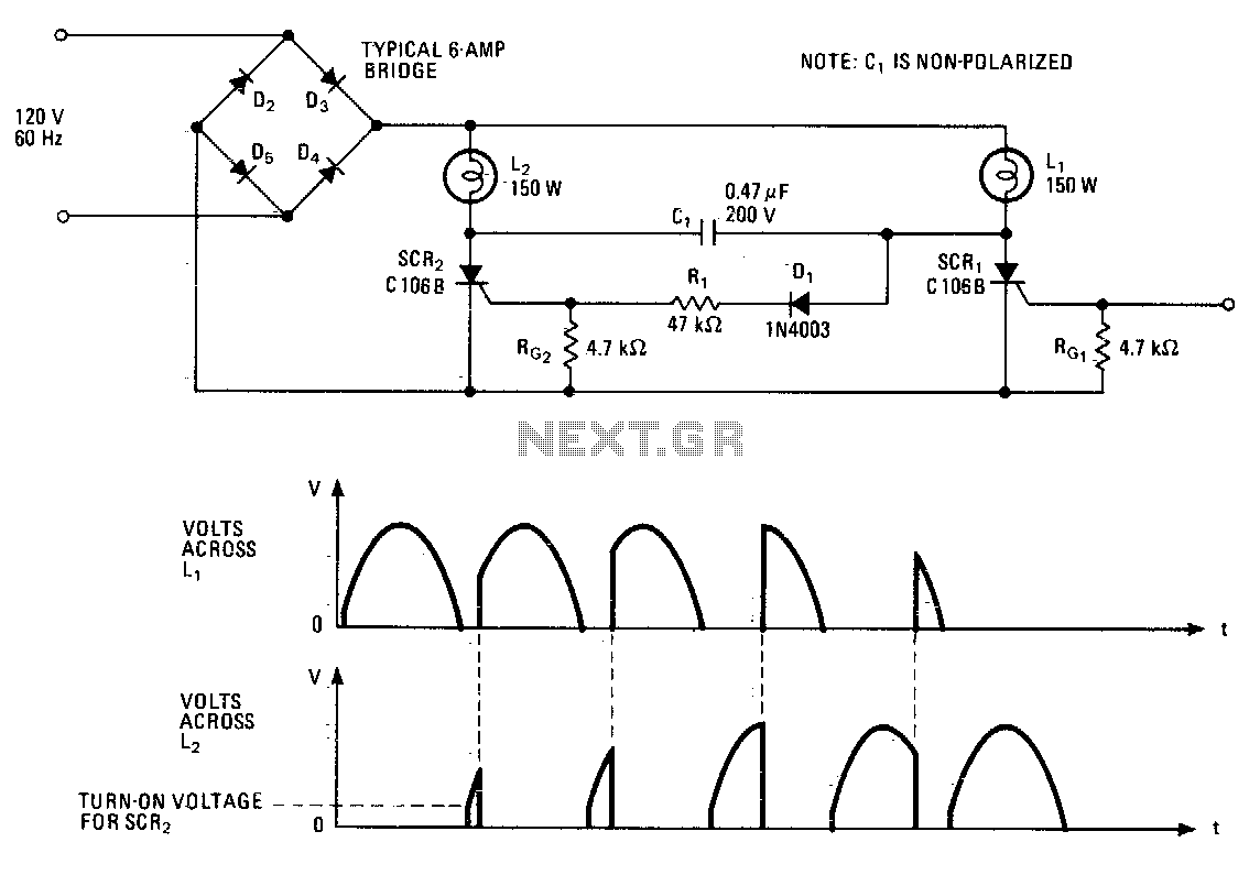
This lighting control unit will gradually decrease the brightness of one lamp while simultaneously increasing the brightness of another. The two loads maintain precise tracking without the need for manual adjustments. The gate of SCR1, a silicon-controlled rectifier, is...
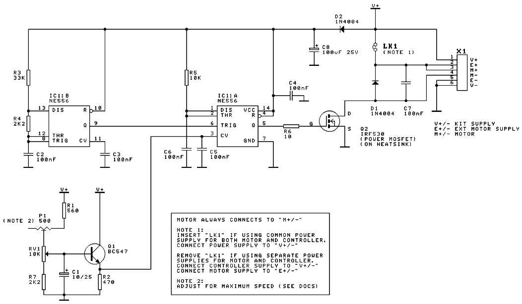
A DC motor speed controller circuit utilizes two timers configured as a Pulse Width Modulator (PWM). The integrated circuit employed for this purpose is the NE556, which is a dual timer/oscillator using NMOS technology. The DC motor speed controller circuit...