
Assemble the AVR Tiny MIcrocontroller Circuit
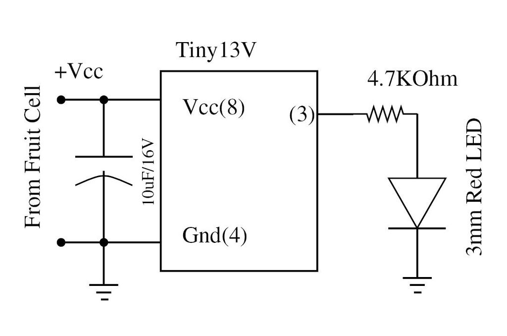
To successfully implement the circuit diagram on a breadboard, several considerations must be taken into account. The AVR microcontroller, specifically the ATtiny13V, is a compact, low-power option suitable for various applications, particularly in embedded systems. This microcontroller operates at a voltage range of 1.8V to 5.5V, making it versatile for battery-powered projects.
When wiring the circuit, it is essential to ensure that the power supply voltage corresponds to the requirements of the ATtiny13V. The microcontroller should be connected to a stable power source, with appropriate decoupling capacitors placed close to its power pins to minimize noise and voltage fluctuations. Typically, a 0.1µF capacitor is used for decoupling.
The input and output pins of the ATtiny13V must be configured according to the intended application. For example, if the circuit involves interfacing with sensors or actuators, the corresponding pins should be connected to the respective components. Pull-up or pull-down resistors may be necessary to ensure proper logic levels are maintained on the input pins.
Moreover, it is advisable to incorporate a reset button in the design to allow for easy reinitialization of the microcontroller. This button should be connected to the reset pin, typically with a pull-up resistor to the Vcc.
For programming the ATtiny13V, a suitable programmer must be connected to the appropriate pins on the microcontroller. The ISP (In-System Programming) interface is commonly used for this purpose, allowing for easy updates and modifications to the firmware.
In summary, careful attention to the wiring and configuration of the ATtiny13V on the breadboard will facilitate successful operation of the circuit, ensuring that all components are properly connected and that the microcontroller receives the necessary power and signals for its intended function.Wire the circuit diagram shown here on a bread board. The choice of V type of AVR is important. For example Tiny13V is very appropriate for such an ex.. 🔗 External reference
Related Circuits
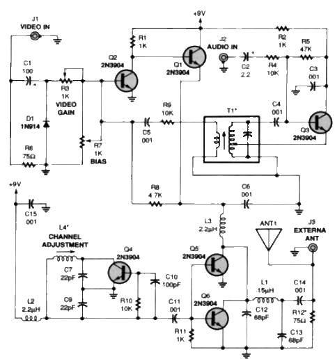
A simple TV audio-video transmitter circuit can be designed using this schematic diagram. This circuit can transmit video signals from a VCR or other devices to a TV without the need for cables. Video signals input at jack J1...

The VLF whistler receiver is designed to detect natural radio noise and signals that occur below 20 kHz. LI is a large loop antenna consisting of 250 to 300 turns of #26 gauge wire wound on a form with...
This circuit allows the use of an inexpensive loudspeaker as a microphone. Sound waves that reach the speaker cone cause fluctuations in the voice coil. The movement of the voice coil within the speaker's magnetic field generates a small...
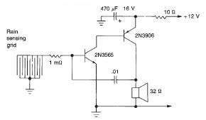
This rain detector electronic circuit project is a simple alarm circuit that activates an audio warning when liquid is detected on the sense pad. The circuit diagram is based on two transistors. When the sense pad conducts, transistors Tr1...
This circuit provides a straightforward and efficient method for interfacing two relays in switching applications. The relay driver utilizes a standard BC547 NPN transistor (or equivalent) to enhance the input impedance. It is a widely used driver capable of...

The local oscillator operates at frequencies of 1 GHz or higher, utilizing a common collector circuit, which makes it challenging to generate low-frequency self-oscillation. Typically, the local oscillator signal is passed through a buffer amplifier stage before being applied...