
DC Motor Speed Controller

The DC motor speed controller circuit operates by varying the duty cycle of the PWM signal generated by the NE556 timer. This modulation of the PWM signal directly influences the average voltage applied to the DC motor, thereby controlling its speed. The NE556 timer is capable of functioning in both astable and monostable modes, allowing for flexible control strategies.
In this circuit, the two timers can be configured to operate in an astable mode, generating a continuous square wave output. The frequency of this output can be adjusted by selecting appropriate resistor and capacitor values connected to the timer's pins. The duty cycle of the PWM signal can be fine-tuned by altering the ratio of these resistors, which determines the time the output remains high versus low.
The output from the NE556 is connected to a power transistor, typically an NMOS or a MOSFET, which acts as a switch to control the power delivered to the DC motor. When the PWM signal is high, the transistor conducts, allowing current to flow to the motor, and when the signal is low, the transistor turns off, stopping the current flow. This rapid switching creates an average voltage that the motor experiences, effectively controlling its speed.
Additionally, incorporating feedback mechanisms such as an encoder or tachometer can enhance the performance of the speed controller by providing real-time speed data to adjust the PWM signal dynamically. This feedback loop ensures that the motor maintains a desired speed under varying load conditions, improving efficiency and responsiveness.
Overall, the use of the NE556 in this DC motor speed controller circuit provides a robust and versatile solution for applications requiring precise speed control, making it suitable for various industrial and hobbyist projects.DC motor speed controller circuit, applies two timers connected as a Pulse Width Modulator. The chip put into use will be an nmos dual timer/oscillator NE556 🔗 External reference
Related Circuits
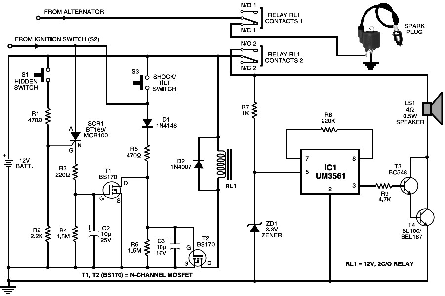
This is a cost-effective motorcycle alarm circuit. During parking, a hidden switch S1 remains normally open, preventing the triggering of MOSFET T1. When the motorcycle is started using ignition switch S2, MOSFET T2 is activated through diode D1 and...
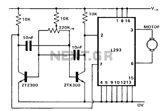
The control of both direction and proportional motor speed is accomplished through the rotation of a single potentiometer. The motor driver utilized is the SGS integrated circuit L293, which can drive up to 1 amp in either direction, depending...
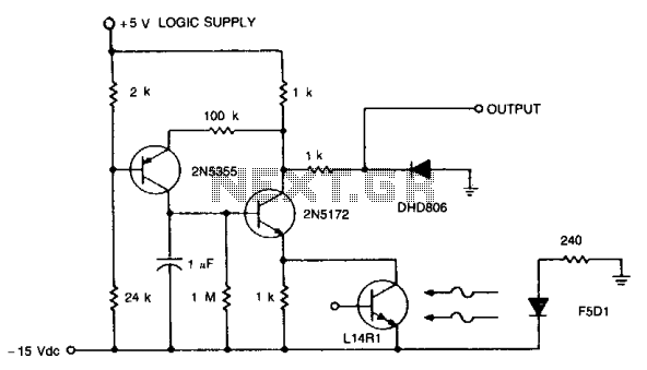
When interfacing computer peripheral equipment, it is advantageous to utilize logic signal levels. This circuit operates with a nominal output of 4 V, which drops to -0.6 V upon illumination, meeting the specifications for a high-speed optical reader system...
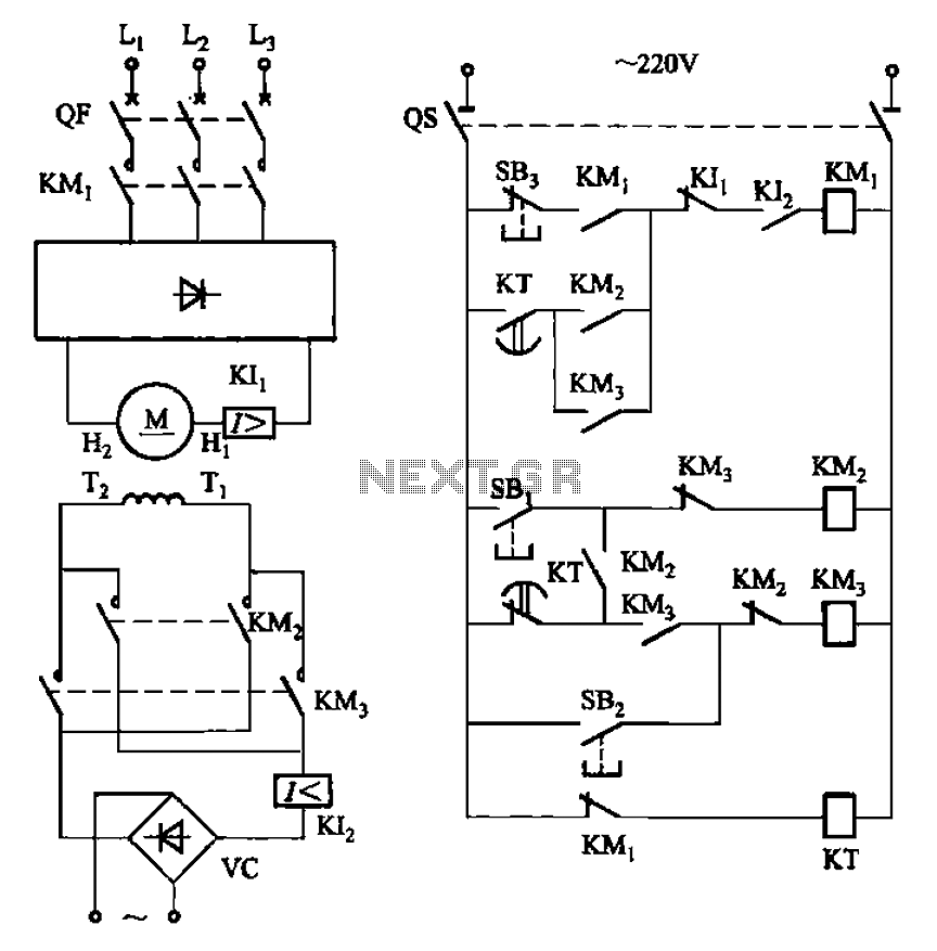
The circuit depicted in Figure 3-193 illustrates a separately excited DC motor. The brake circuit is not activated; therefore, positive reversals occur alternately using a delay action relay, ensuring that the motor reverses direction after coming to a stop. The...
As summer approaches, many individuals focus on staying cool during hot days. For some, this means turning on the air conditioner and enjoying a cold beverage. However, it is essential to consider how to maintain the temperature of radio...
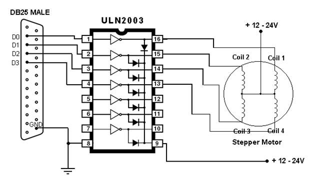
This article outlines the process of connecting a stepper motor to a computer's parallel port and writing code to control it using the scroll wheel of a mouse. For those unfamiliar with stepper motors, this project offers an engaging...