
Integrated operational amplifier tone control circuit of a simplified equivalent circuit a
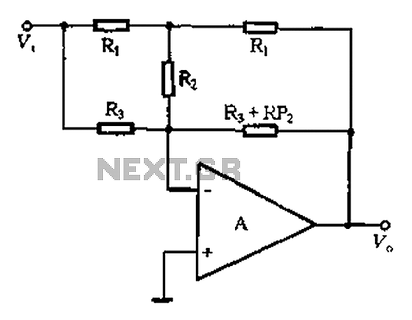
At high frequencies, the behavior of capacitors and resistors within a circuit significantly influences the overall performance. In this context, capacitor Cz is effectively acting as a short circuit, which simplifies the analysis of the circuit by removing the impedance of the RPi. This allows for a clearer understanding of how the remaining components interact under high-frequency conditions.
The maximum lifting capacity formula indicates how the circuit can handle power at elevated frequencies, taking into account the resistances R1, R3, and R2. Each of these resistors contributes to the total impedance experienced by the circuit, and their values must be optimized to achieve desired performance characteristics.
The maximum high-frequency attenuation value provided by the equation shows how the signal strength diminishes as it passes through the circuit. This attenuation is critical in applications where signal integrity is paramount, such as communication systems or high-speed digital circuits.
The assumption that RP2 equals the sum of R1, R3, and twice R2 is essential for simplifying circuit calculations and ensuring accurate modeling of the system's response. This relationship illustrates how the resistive elements work together to define the overall impedance.
Finally, the high-frequency boost corner frequency formula indicates the frequency at which the circuit begins to exhibit significant gain, determined by the resistor R3 and capacitor C2. This frequency is crucial for applications requiring specific bandwidths, as it dictates the operational limits of the circuit. The use of standard units for resistance and capacitance ensures that the calculations can be universally applied and understood within the field of electronics. At high frequencies, q, Cz can be seen as a short circuit (i.e. RPi not present), as shown in Figure 4-6 (a) in the apparatus shown in FIG equivalent to 4-6 (b). Then there are : a high-frequency maximum lifting capacity: A f F (RI + R3 + 2Rz) cuddle 3; maximum high-frequency attenuation value: vc F feet 3/(Ri + R3 ten 2Rz). On two formula assumes: RP2 (Rt ® 3 + 2R2), high-frequency boost corner frequency:, s l/. 7tR3 C2. (Unit: f a ratio, R- fl (Europe), C- F (scared))
Related Circuits
Instructions for constructing and utilizing a basic PIC programmer using readily available and inexpensive components. The total cost for building the programmer is under $1.50. The simple PIC programmer is designed to facilitate the programming of PIC microcontrollers, which are...
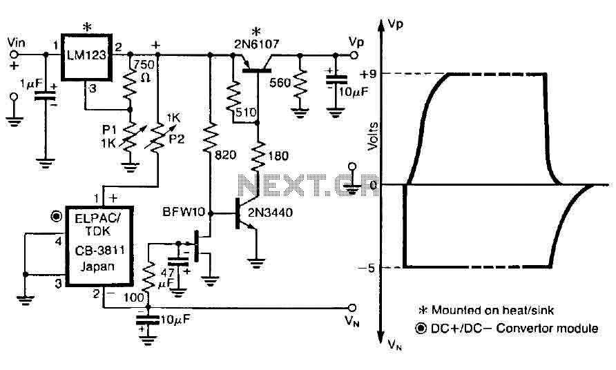
The control circuit is designed to operate by doubling a positive supply, which activates the first door when powered on and deactivates when the first drain is engaged, as illustrated in the accompanying figure. This circuit incorporates the LM123,...
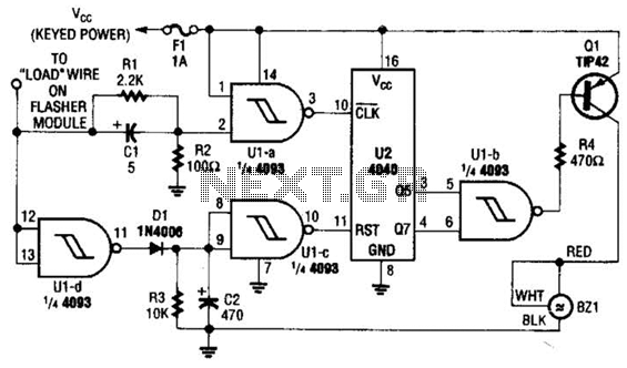
This circuit counts the flashes of turn signals. After approximately 70 flashes, a chime sounds to remind the driver to deactivate the turn signal. The period can be altered by using different taps on U2 if desired. BZ1 serves...

A basic LED driver circuit consists of a 5-volt power source, a 2 kΩ potentiometer, and an LED. The LED is forward biased, with the manufacturer specifying a maximum current rating of 20 mA at a diode voltage drop...
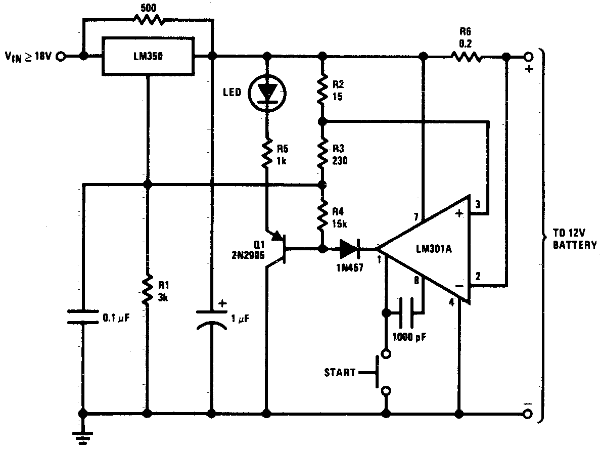
DC 12V Battery Charger Circuit Diagram. This circuit is a high-performance charger for gelled electrolyte lead-acid batteries. The DC 12V battery charger circuit is designed to efficiently charge gelled electrolyte lead-acid batteries, which are commonly used in various applications due...
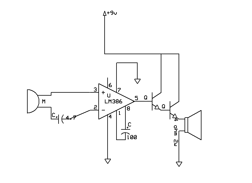
The sound quality was poor, and then it stopped functioning. Can anyone explain which part of the circuit may have malfunctioned? Any suggestions to enhance the sound quality and restore functionality? The transistors used are both BC546, and the...