
Ni-cad charger with current and voltage limiting
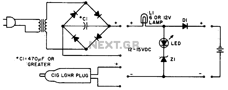
The described circuit operates as a battery charging indicator and protection mechanism. The main components include a light bulb (LI), an LED, a diode (D1), and a Zener diode (Z1). The light bulb serves as a visual indication of the charging state of the battery. When the battery voltage is low, the circuit allows for a higher current draw, illuminating the light bulb brightly to signal that charging is in progress. The LED remains off during this state to prevent confusion about the charging status.
As the battery approaches full charge, the circuit transitions to a lower current state. In this condition, the LED lights up brightly, indicating that the battery is nearly charged, while the light bulb dims due to reduced current flow. This dual indication helps users easily monitor the charging process and the battery's health.
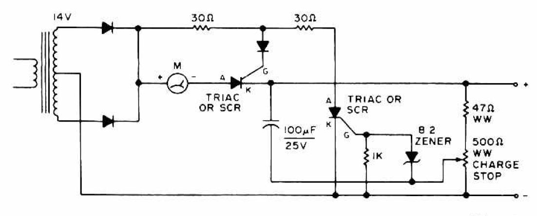
The diode (D1) is critical for ensuring that the current does not exceed 1 A, protecting the circuit from potential damage due to excessive current. The Zener diode (Z1) plays a vital role in voltage regulation; it is selected based on the full-charge voltage of the battery, minus a 1 V margin to allow for safe operation without overcharging.
Once fully charged, the circuit enters a float charge mode, where it maintains a small current, approximately equal to the battery capacity divided by 100 mA. This float charging is essential for maintaining the battery's charge without overcharging, thereby extending its life and ensuring reliable performance. The design of this circuit provides a straightforward and effective solution for battery management, combining visual indicators with protective components to enhance usability and safety.Lamp LI will glow brightly and the LED will be out when the battery is low and being charged, but the LED will be bright and the light bulb dim when the battery is almost ready. Ll should be a light bulb rated for the current you want (usually the battery capacity divided by 10).
Diode D1 should be at least 1 A, and Z1 is a 1W zener diode with a voltage determined by the full-charge battery voltage minus 1 V After the battery is fully charged, the circuit will float it at about battery capacity divided by 100 mA. 🔗 External reference
Related Circuits
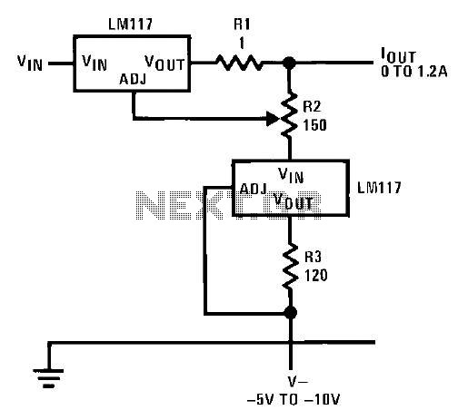
This circuit illustrates an adjustable regulator configuration that incorporates a voltage regulator. In this design, the LM117 regulator is utilized instead of the LM113 diode for reference. Both regulators necessitate a negative supply to function correctly with respect to...
Here's how to make a good charger for a sealed lead-acid battery (this will NOT work with NiCad batteries) that’s faster (because it allows more current into the battery initially) and safer (because it uses lower voltage when the...
A distribution substation is defined by the apparent power of the transformer and its configuration, which can be aerial, terrestrial, or underground. A distribution substation plays a critical role in the electrical power distribution network. It serves as a point where...
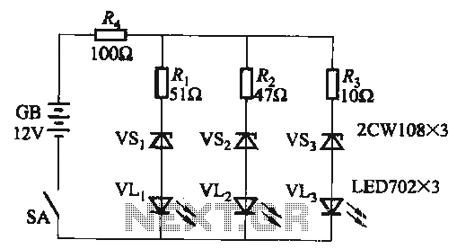
When the supply voltage falls below 10.2V, the yellow light-emitting diode (LED) VLi illuminates, indicating that the storage pool can no longer continue to discharge. Additionally, when the voltage exceeds 16.2V, the yellow, green, and red light-emitting diodes (LEDs)...
The charging circuit features adjustable voltage output settings, allowing for regulation of the charging voltage supplied to the battery. The use of a potentiometer facilitates precise voltage management, with adjustments possible down to the millivolt range. Refer to the...
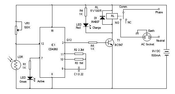
Timer for Charger Circuit Diagram. This timer circuit assists in maintaining the battery in optimal condition by enabling automatic charging for 5 to 6 hours daily, allowing the device to be left unattended. The timer circuit for the charger is...