
Voltage Inverter
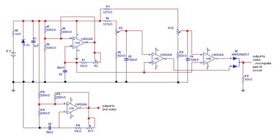
The described circuit utilizes a 555 timer configured in an astable mode to generate a square wave signal. This square wave is then applied to a transformer or an inductor, which is used to step up the voltage, allowing for the generation of a negative supply voltage from a positive input. The output from the transformer is rectified using a diode bridge, ensuring that the negative voltage is correctly oriented for use by the op-amp.
The key components include:
1. **555 Timer**: This integrated circuit serves as the oscillator, generating a continuous square wave output that drives the transformer.
2. **Transformer/Inductor**: This component is crucial for voltage inversion; it steps up the voltage from the 555 timer's output to a level suitable for the op-amp's negative supply.
3. **Diode Bridge**: Comprising four diodes, this component rectifies the AC output from the transformer into a usable DC voltage.
4. **Capacitors**: These are used for filtering the output to smooth out the rectified voltage, ensuring stable operation for the op-amp.
5. **Resistors**: These components are used to set the frequency of the 555 timer and may also be involved in biasing the op-amp.
The circuit's simplicity and low component count make it an attractive solution for applications requiring a dual supply voltage from a single battery source, such as portable audio equipment, sensor systems, and other low-power devices. The design also allows for easy adjustments to the output voltage levels by changing the transformer turns ratio or the values of the timing components in the 555 timer circuit. Overall, this circuit presents a cost-effective and efficient method for powering dual-supply operational amplifiers in various electronic applications.This simple circuit is a good solution to the powering a dual supply op amp from a single battery problem. The circuit simply takes a positive voltage and inverts it. It uses only one 555 timer and a few other passive components, so it doesn`t add much in the way of size and cost to a project.
🔗 External reference
Related Circuits
The LM317T is an adjustable three-terminal positive voltage regulator capable of supplying more than 1.5 amps with an output range of 1.25 to 37 volts. The device features built-in current limiting and thermal shutdown, making it robust against failure....
The MAX6499 includes undervoltage and overvoltage comparators for window detection. When the monitored voltage is within the selected window, the GATE is enabled. The MAX6499 is a precision voltage monitoring device designed to detect both undervoltage and overvoltage conditions within...
This low voltage circuit can be used to monitor batteries and other volatile sources of current for problems. The circuit sounds an alarm and lights an LED, but can be interfaced to any number of other circuits for many...
This circuit utilizes an LM339 quad voltage comparator to create a time delay and manage a high current output at low voltage levels. Approximately 5 amps of current can be sourced using a pair of fresh alkaline D batteries....
The goal is to control the speed of a 6-volt brush DC motor using a linear potentiometer and to create an oscillating speed effect, with the oscillation frequency also adjustable via a linear potentiometer. The desired complete cycle peak-to-peak...
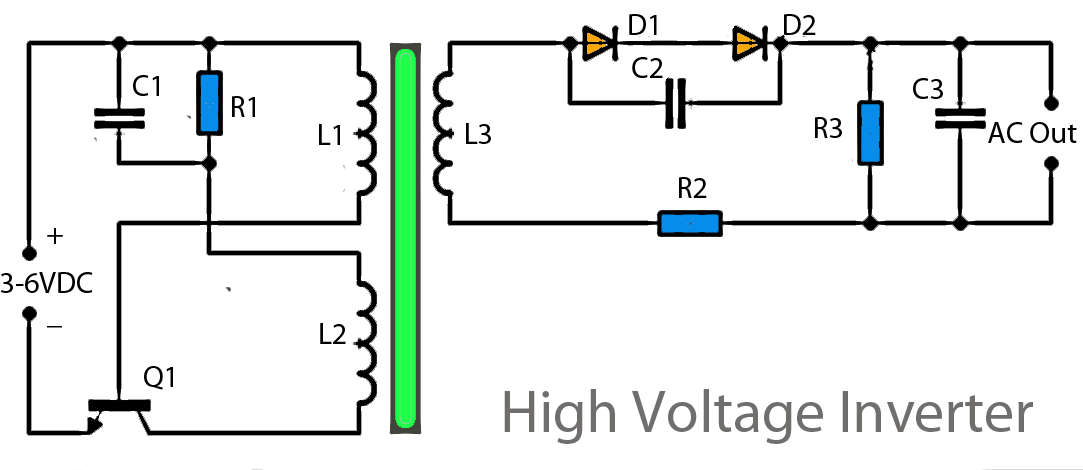
This inverter circuit operates using a transistor and transformer, along with other components, to elevate the voltage. The input supply voltage ranges from 3V to 6V DC, which is then converted to a high voltage AC output. However, the...