
12 Volt Lamp Dimmer schematic
The circuit described operates on a 12V power supply and is designed to control the brightness of a 25W automotive bulb, commonly used for brake or backup lights. At the core of this dimmer circuit is the 555 timer configured in an astable mode, which generates a continuous square wave output. The frequency of this output is set at approximately 200 Hz, which is suitable for dimming applications as it is fast enough to avoid noticeable flicker in the lamp.
The circuit utilizes two 1K ohm resistors and a variable 50K ohm potentiometer to control the charging and discharging cycles of a capacitor. The charging path for the capacitor varies depending on the position of the potentiometer wiper. When the wiper is positioned at the uppermost end, the capacitor charges rapidly through both 1K resistors and a diode, resulting in a shorter positive pulse and longer negative pulse. This configuration effectively reduces the average power delivered to the lamp, dimming it to a near-dark state.
Conversely, when the potentiometer wiper is at the lowermost position, the capacitor charges through the two 1K resistors and the 50K potentiometer while discharging through the lower 1K resistor. This configuration results in a longer positive pulse and a shorter negative pulse, allowing more power to reach the lamp and brightening it to near full intensity.
The duty cycle of the output square wave can be adjusted anywhere from approximately 5% (minimum brightness) to 95% (maximum brightness), providing a wide range of dimming options. The connection configurations for the lamp allow it to be connected either to the positive or negative side of the power supply, providing flexibility in circuit design and implementation. This dimmer circuit is particularly useful in automotive applications where varying light intensity is required for safety and visibility.Here is a 12 volt / 2 amp lamp dimmer that can be used to dim a standard 25 watt automobile brake or backup bulb by controlling the duty cycle of a astable 555 timer oscillator. When the wiper of the potentiometer is at the uppermost position, the capacitor will charge quickly through both 1K resistors and the diode, producing a short positive interval and long negative interval which dims the lamp to near darkness.
When the potentiometer wiper is at the lowermost position, the capacitor will charge through both 1K resistors and the 50K potentiometer and discharge through the lower 1K resistor, producing a long positive interval and short negative interval which brightens the lamp to near full intensity. The duty cycle of the 200 Hz square wave can be varied from approximately 5% to 95%. The two circuits below illustrate connecting the lamp to either the positive or negative side of the supply.
🔗 External reference
Related Circuits
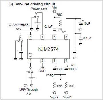
The NJM2670 is a general-purpose 60V dual H-bridge drive integrated circuit (IC). It features a pair of H-bridges, a thermal shutdown circuit, and an alarm output. The alarm output is capable of detecting application issues, thereby significantly enhancing system...
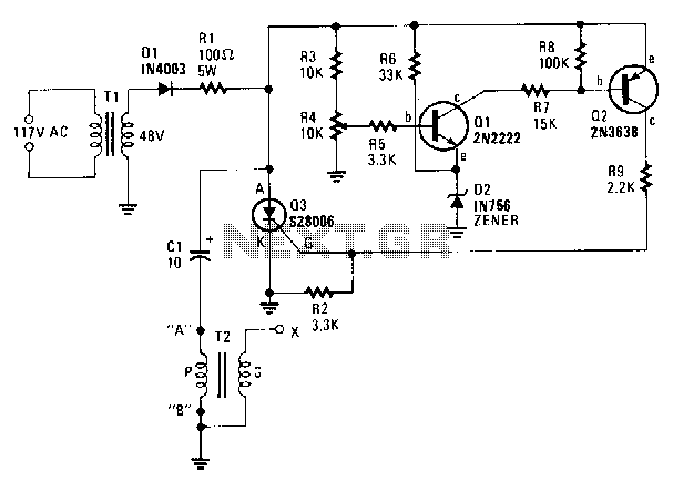
A step-down transformer T1 reduces the incoming line voltage to approximately 48 Vac, which is then rectified by diode D1. The resulting direct current charges capacitor C1 through a current-limiting resistor R1 to a voltage level set by R4....
This is a low-cost project for 20 or 40 watt fluorescent tubes. However, the most efficient is to use a 40 watt tube (or two 20 watt tubes in series). It's a circuit you can put together from junk...
This USB circuit utilizes an integrated circuit (IC) to convert digital voice data into an analog format, making it suitable for headphone use. Additionally, the output can be amplified through a power amplifier, allowing the sound to be played...
As the demand for VRM output current increases, the components and parts of the SR-Buck converter can no longer meet the requirements for the new generation microprocessors needing 100 A. Additionally, creating filtering inductance for high currents is quite...
The fundamentals of crystals have not changed since this article appeared in a 1960 edition of Popular Electronics. The methods for growing, cutting, and packaging crystals have evolved significantly. Understanding their operation at the atomic level has also advanced...
Warning: include(partials/cookie-banner.php): Failed to open stream: Permission denied in /var/www/html/nextgr/view-circuit.php on line 713
Warning: include(): Failed opening 'partials/cookie-banner.php' for inclusion (include_path='.:/usr/share/php') in /var/www/html/nextgr/view-circuit.php on line 713